
Concept explainers
Videos
For the network in Fig. 7.70.
a. Does
b. If
c. Does
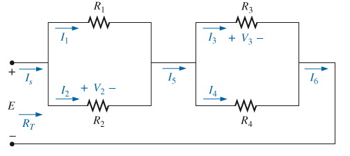
Fig. 7.70
d. If
e. If
f. If all the resistors of the configuration are 20
g. using the values of part (f), find the power delivered by the battery and the power absorbed by the total resistance RT
Want to see the full answer?
Check out a sample textbook solution
Chapter 7 Solutions
Introductory Circuit Analysis (13th Edition)
Additional Engineering Textbook Solutions
Basic Engineering Circuit Analysis
Fundamentals of Applied Electromagnetics (7th Edition)
Electric Circuits (10th Edition)
Principles Of Electric Circuits
Electrical Engineering: Principles & Applications (7th Edition)
ELECTRICITY FOR TRADES (LOOSELEAF)


- 11. For the series-parallel network of Fig. 7.59: a. Find the current I. R2 9. b. Find the currents I3 and I9. c. Find the current Ig. d. Find the voltage V. 50 V. R31 ab. R7 R,10 0 80 V R9 R4 = 42- R58N FIG. 7.59 Problem 11.arrow_forward4_59407736683332... Problem II SERIES-PARALLEL NETWORKS *21. For the network of Fig. 7.84: a. Determine the current /. b. Calculate the open-circuit voltage V *22. For the network of Fig. 7.85, find the resistance current through it is 2 A. 20 V R E120 80 120 V 18 V 60 R200 30 FIG. 7.84 Problem 21. FIG. 7.85 Problem 22arrow_forward276 ||| SERIES-PARALLEL CIRCUITS *7. For the network in Fig. 7.67: a. Find currents I, I, and l b. Find voltages V, and V c. Find the power delivered to the 3 kfl resistor *& For the series-parallel configuration in Fig. 7.68 a. Find the source current , b. Find currents, and/ e. Find current l d. Find voltage V R₁1052 80 V = R₂ W 50 +20 V 50 592 w 4 R. 3802 ww 601 R₁4 R₁80 R, 212 + FIG. 7.68 Problem 8. FIG. 7.69 Problem 9. 9. Determine the currents /, and I, for the network in Fig. 7.69. 16 1 R₂ W www 250 12. For the network in Fig. 7.72: a. Determine the current 7. b. Calculate the currents I, and 1₂. e. Determine the voltage levels V, and V 8 20V M 8,30 [+ R₂30 R, GURGU FIG. 7.72 Problem 12. 48 V E = 28 V TOV R₂40 -79 R₂ *13. Determine the de levels for the transistor network in Fig. 7.73 using the fact that Vas-0.7 V, V-2V, and Ic - Ig That is a. Determine I, and lo -1k0 114 41242² FIG. 7.66 Problem 6 FIG. 7.67 Problem 7. R, 401 1₁ ly 4,340 R₂ 10. a. Find the magnitude and…arrow_forward
- *11. For the series-parallel network of Fig. 7.74: R2 R6 a. Find the current I. b. Find the currents I and Ig. c. Find the current Ig. d. Find the voltage Vab 6Ω V 19 at Ro 60 1s R1 10 Ω 80 V 4Ω R = 40 Rs8N R20 FIG. 7.74 Problem 11.arrow_forward1. For the network in Fig. 7.70: a. Does Is = I5 = I6? Explain. b. If Is = 10 A and I1 = 4 A, find I2. c. Does I1 + I2 = I3 + I4? Explain. d. If V2 = 8 V and E = 14 V, find V3. e. If R1 = 4 Ω, R2 = 2 Ω, R3 = 4 Ω, and R4 = 6 Ω, what is RT? f. If all the resistors of the configuration are 20 Ω, what is the source current if the applied voltage is 20 V? g. Using the values of part (f), find the power delivered by the battery and the power absorbed by the total resistance RT.arrow_forward1:0r 1%EM とイ l المكالمات H.W -2 6. For the circuit board in Fig. 7.66: a. Find the total resistance R, of the configuration. b. Find the current drawn from the supply if the applied voltage is 48 V. c. Find the reading of the applied voltmeter. 6.8 kf2 V 3.3 kfl 2 k Rr 1 k -24 kf 48 V FIG, 7,66 Problem 6.arrow_forward
- For the ladder network in fig . 7.90 A. Find the current I B.Find the current I7 C.determine the voltage V3 V5 and V7 D. Calculate the power delivered to R7 and compare it to the power delivered by the 240 V supplyarrow_forward14. For the network of Fig. 7.86, Vp = 12 V. Determine: a. Ip. b. Vs and Vps- c. Vg and VGs. d. Vp.arrow_forwardQ2 o 20 V For the network of Fig. 7.85, determine: 2.2 kn a. VG- b. Ipo and VGSo c. Vp and Vs- d. Vpsg 910 k2 DO Dss = 10 mA Vp =-3.5 V VG +] Vaso 110 kΩ 1.1 k2arrow_forward
- FET BIASING 33. For the network of Fig. 7.102, determine: a. Ip, and VGso' b. Vps- c. Vp. C9 9-16 V 2 k2 1 M2 VGs (Th) = -3 V Ip (on) = 4 mA VGs (on) = -7 V Vase FIG. 7.102arrow_forward*21. For the network of Fig. 7.93, determine: a. Ipo and VGSo b. Vps and Vs. 18 V 2.2 k2 Ipss = 8 mA Vp = -8 V Vaso 0.39 k2 6-4 V FIG. 7.93 Problem 21.arrow_forward. Determine Vp and VGs for the network of Fig. 7.91 using the provided information. VD 4 V 1.8 k2 1 k2 16 V o- VGS Dss= 4 mA Vp=-6 V 3.6 kn 1.2 kNarrow_forward
 Introductory Circuit Analysis (13th Edition)Electrical EngineeringISBN:9780133923605Author:Robert L. BoylestadPublisher:PEARSON
 Delmar's Standard Textbook Of ElectricityElectrical EngineeringISBN:9781337900348Author:Stephen L. HermanPublisher:Cengage Learning
 Programmable Logic ControllersElectrical EngineeringISBN:9780073373843Author:Frank D. PetruzellaPublisher:McGraw-Hill Education
 Fundamentals of Electric CircuitsElectrical EngineeringISBN:9780078028229Author:Charles K Alexander, Matthew SadikuPublisher:McGraw-Hill Education
 Electric Circuits. (11th Edition)Electrical EngineeringISBN:9780134746968Author:James W. Nilsson, Susan RiedelPublisher:PEARSON
 Engineering ElectromagneticsElectrical EngineeringISBN:9780078028151Author:Hayt, William H. (william Hart), Jr, BUCK, John A.Publisher:Mcgraw-hill Education,