
Concept explainers
Videos
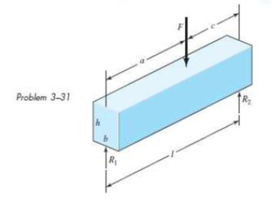
The Roman method for addressing uncertainty in design was to build a copy of a design that was satisfactory and had proven durable. Although the early Romans did not have the intellectual tools to deal with scaling size up or down, you do. Consider a simply supported, rectangular-cross-section beam with a concentrated load F, as depicted in the figure. (a) Show that the stress-to-load equation is
(b) Subscript every parameter with m (for model) and divide into the above equation. Introduce a scale factor, s = am/a = bm/b = cm/c etc. Since the Roman method was to not “lean on” the material any more than the proven design, set σm/σ = 1. Express Fm in terms of the scale factors and F, and comment on what you have learned.
Want to see the full answer?
Check out a sample textbook solution
Chapter 3 Solutions
Shigley's Mechanical Engineering Design (McGraw-Hill Series in Mechanical Engineering)


- A seesaw weighing 3 lb/ft of length is occupied by two children, each weighing 90 lb (see figure). The center of gravity of each child is 8 ft from the fulcrum. The board is 19 ft long, 8 in. wide, and 1.5 in. thick. What is the maximum bending stress in the board?arrow_forwardAn aluminum bar has length L = 6 ft and diameter d = 1.375 in. The stress-strain curse for the aluminum is shown in Fig. 1.34. The initial straight, line part of the curve has a slope (modulus of elasticity) of 10.6 × 10⁶ psi. The bar is loaded by tensile forces P = 44.6 k and then unloaded. (a) That is the permanent set of the bar? (b) If the bar is reloaded. what is the proportional limit? hint: Use the concepts illustrated in Figs. l.39b and 1.40.arrow_forwardA two-story building has steel columns AB in the first floor and BC in the second floor, as shown in the figure. The roof load P:equals 400 KN, and the second-floor load P-, equals 720 kN. Each column has a length L = 3.75 m. The cross-sectional areas of the first- and second-floor columns are 11,000 mm" and 3900 mm", respectively. (a) Assuming that E = 206 GPa. determine the total shortenings aof the two columns due to the combined action of the loads Ptand P,. (b) How much additional load P0can be placed at t he top of t he column (point C) if t he total shortening: SACis not to exceed 4.0 mm?arrow_forward
- Solve the preceding problem if the diameter is 480 mm, the pressure is 20 MPa, the yield stress in tension is 975 MPa, the yield stress in shear is 460 MPa, the factor of safety is 2,75, the modulus of elasticity is 210 GPa, Poissorfs ratio is 0.28, and the normal strain must not exceed 1190 x 10" . For part (b), assume that the tank thickness is 8 mm and the measured normal strain is 990 x 10~ .arrow_forwardA tie-down on the deck of a sailboat consists of a bent bar boiled at both ends, as shown in the figure. The diameter dBof the bar is 1/4 in., the diameter D Wof the washers is 7/8 in., and the thickness is of the fiberglass deck is 3/8 in. If the allowable shear stress in the fiberglass is 300 psi, and the allowable bearing pressure between the washer and the fiberglass is 550 psi, what is the allowable load P allowon the tie-down?arrow_forwardA bar of a uniform cross-section is rigidly fixed at one end and loaded by an off-centre tensile point load F = 2.5 kN at the other end, see Fig. Q1a. The Figure Q1b presents the view of the beam from the free end where the point of application of the load F is indicated as A. The allowable stress [σ]=269 MPa The geometrical parameters are given as follow h=17 mm , b=48 mm the magnitude of the maximum normal stress in the beam and where within the beam it is achieved. a) Find the bending moment relative to z-axis Mz on the cross section b) Find the bending moment relative to y-axis My on the cross section c)The second moment of area relatve to z-axis d)The second moment of area relative to y-axis e) The magnitude of the maximum normal stress in the beam f)The magnitude of the minimum normal stress in the beamarrow_forward
- Figure 1 shows a composite shaft ABCD acted upon horizontal forces. The moduli of elasticity and the cross-section areas of the segments of the shaft are also provided. Eal = 70 GPa AAB = 58 mm2 Ecu = 126 GPa Est AcD = 39 mm2 = 200 GPa ABC = 77 mm2 %3D %3D Copper 20kN 8 kN Aluminum Steel 7 kN A B 20kN D 8 kN 450 mm 300 mm - 400 mm Figure 1: Axially loaded composite shaft 2.1. Construct the diagram of internal normal forces for each cross-section of the shaft (6) 2.2. Calculate the displacement of the point C with respect to the fixed-point A. (3) 2.3. If the shaft must have one uniform diameter, determine the required minimum diameter of the shaft if the normal yield stress in the composite shaft must not exceed 450 MPa with a factor of safety equal to 1.8. (11)arrow_forward3. A cylindrical rod is fixed between two walls. The rod is composed of two materials. Section AC is made of one material (GAC = 2G) while section CD is made of a different material (GcD = G). A torque, T, is applied at point B, as shown below. Jac = JcD = J = 2 in. GẠC = 2G = 20 x 10ʻ psi T= 300 kip in. GCD = G = 10 × 106 psi A D 2L Determine the reactions at the wall, Ta, and Tp. Specify the direction for each. (Note: this is an example of a no calculator problem.) Ans: TA = 250 kip in ( Tp=50 kip in ( T Fixed Fixed to wall to wallarrow_forwarda) Figure Q4 (a) shows an L-bracket ABC which lies in the horizontal plane. It is made from a material with elastic and shear moduli E and G, respectively. If a vertical load Pis applied at end C, determine the total strain energy that is stored in the whole structure. Express your answer in tems of P, E, G, I and J. Neglect the strain energy due to transverse shear force. b) AL-beam ABC with a diameter of 15 mm shown in Figure Q4 (b) is fixed at.4. It is subjected to a horizontal force of 10 N at B and a vertical force of P at C. The material has an elastic and shear moduli of 200 GPa and 70 GPa, respectively. Use Castigliano's second theorem and consider bending effects ONLY. (i) What is the value of the vertical force P so that there is NO VERTICAL DISPLACEMENT at C? (ii) By using the value of P obtained from part (i), calculate the slope at C. B 10 N 2 m 3 m 3 m B. 2 m Figure Q4 (a)/Rajah S4(a) Figure Q4 (b)/Rajah S4(b)arrow_forward
- In the figure shown, the cutaway view shows a solid aluminum alloy of L= 600mm, A= 707mm^2 and E= 70GPa rod within a closed-end bronze of L= 610mm, A= 1206mm^2 and E= 100GPa tube. Before the load P is applied, there is a clearance of 2mm between the rod flange at B and the tube closure at A. After load P is applied, the solid aluminum alloy rod stretches enough so that flange B contacts the closed end of the tube at A. If the load applied to the lower end of the aluminum rod is P= 345KN, calculate:A. The normal stress in bronze tube, in MPa.B. The elongation of bronze tube, in mm.arrow_forwardA vertical steel bar shown in figure Q1 is subjected to a compressive load of 75 kN. If the stress in the middle portion is limited to 47 MN/m2, determine its cross-section dimensions. Find also the length of the middle and other portions if the total reduction in length of the bar is to be 0.04 mm. Assume Young's modulus for steel is 200 GN/m². E 200 mm a ID 75 kN Circular D=50 mm Square bxb Circular D=50 mm Figure Q1: Bar Loadings and Sectionsarrow_forwardQUESTION 3 Figure Q3 shows a solid steel rod AB (Esteel = 200 GPa) welded firmly to an aluminium tube BC (Ealuminium = 73 GPa) and it is fixed at A. Given diameter of the steel rod is 50 mm and the inner and outer diameter of the aluminum tube is 50 mm and 100 mm, respectively. Beam is subjected with load P at B. (a) Determine whether this beam is statically determinate of statically indeterminate and clearly explain your reasoning (b) If P = 40 kN is applied and touched the wall at D, find support reactions at each end (c) Find normal stresses in section AB and BC. |A B 400 mm 800 mm 0.4 mm gap Figure Q3arrow_forward
 Mechanics of Materials (MindTap Course List)Mechanical EngineeringISBN:9781337093347Author:Barry J. Goodno, James M. GerePublisher:Cengage Learning