
Shigley's Mechanical Engineering Design (McGraw-Hill Series in Mechanical Engineering)
10th Edition
ISBN: 9780073398204
Author: Richard G Budynas, Keith J Nisbett
Publisher: McGraw-Hill Education
expand_more
expand_more
format_list_bulleted
Concept explainers
Videos
Textbook Question
Chapter 3, Problem 56P
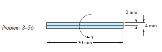
Two 300-mm-long rectangular steel strips are placed together as shown. Using a maximum allowable shear stress of 80 MPa, determine the maximum torque and angular twist, and the torsional spring rate. Compare these with a single strip of cross section 30 mm by 4 mm. Solve the problem two ways: (a) using Eqs. (3–40) and (3–41), and (b) using Eq. (3–47). Compare and discuss your results
Expert Solution & Answer
Want to see the full answer?
Check out a sample textbook solution
Students have asked these similar questions
A steel axle is made from tubes AB and CD and a solid section BC. It is supported on smooth
bearings that allow it to rotate freely. If ends 4 and D are subjected to 85 Nm torques, determine
the angle of twist of end B with respect to C. The tubes have an outer diameter of 30 mm and
inner diameter of 20 mm. The solid section has a diameter of 40 mm. Steel has a shear modulus
of elasticity G = 75 GPa. Provide your final answer in degrees.
The diameter of
and LcD = 240 mm.
1. The lengths LAB = LBC = 200 mm
parts AB and CD of the bar is 25 mm and the diameter of part BC is 50 mm.
The shear modulus of the material is G = 80 GPa. If the torque T = 2.2 kN-
m, determine the magnitude of the angle of twist of the right end of the bar
relative to the wall in degrees.
4 kN-m
8 kN-m
LAB.
LBC.
2. The lengths LAB = LBC = 200 mm and LCD = 240 mm. The diameter of
parts AB and CD of the bar is 25 mm and the diameter of part BC is 50 mm.
The shear modulus of the material is G = 80 GPa. What value of the
torque T would cause the angle of twist of the right end of the bar relative to
the wall to be zero?
4 kN-m
8 kN-m
LAB.
T
LBC
A steel column with an outer
diameter of 50 mm and an inner
diameter of 40 mm surrounds a solid
steel bar with a diameter of 30 mm. A
support at one end of the bar and a
hard plate at the other end of the tube
hold them both tightly in place. A torque
T = 650 Nm acting on the end plate
twists the composite bar, which has a
height of 850 mm. Assuming that the
steel's shear modulus is G = 80 GPa,
find the maximum shear stresses in the bar and tube, respectively, and the angle of rotation (in degrees) of the end plate
Chapter 3 Solutions
Shigley's Mechanical Engineering Design (McGraw-Hill Series in Mechanical Engineering)
Ch. 3 - 31 to 34 Sketch a free-body diagram of each...Ch. 3 - 31 to 34 Sketch a free-body diagram of each...Ch. 3 - Sketch a free-body diagram of each element in the...Ch. 3 - 3-1 to 3-4 Sketch a free-body diagram of each...Ch. 3 - 35 to 38 For the beam shown, find the reactions at...Ch. 3 - 35 to 38 For the beam shown, find the reactions at...Ch. 3 - 35 to 38 For the beam shown, find the reactions at...Ch. 3 - For the beam shown, find the reactions at the...Ch. 3 - For the beam shown, find the reactions at the...Ch. 3 - Repeat Prob. 36 using singularity functions...
Ch. 3 - Repeat Prob. 37 using singularity functions...Ch. 3 - Repeat Prob. 38 using singularity functions...Ch. 3 - For a beam from Table A9, as specified by your...Ch. 3 - A beam carrying a uniform load is simply supported...Ch. 3 - For each of the plane stress states listed below,...Ch. 3 - Repeat Prob. 315 for: (a)x = 28 MPa, y = 7 MPa, xy...Ch. 3 - Repeat Prob. 315 for: a) x = 12 kpsi, y = 6 kpsi,...Ch. 3 - For each of the stress states listed below, find...Ch. 3 - Repeat Prob. 318 for: (a)x = 10 kpsi, y = 4 kpsi...Ch. 3 - The state of stress at a point is x = 6, y = 18, z...Ch. 3 - The state of stress at a point is x = 6, y = 18, z...Ch. 3 - Repeat Prob. 320 with x = 10, y = 40, z = 40, xy =...Ch. 3 - A 34-in-diameter steel tension rod is 5 ft long...Ch. 3 - Repeat Prob. 323 except change the rod to aluminum...Ch. 3 - A 30-mm-diameter copper rod is 1 m long with a...Ch. 3 - A diagonal aluminum alloy tension rod of diameter...Ch. 3 - Repeat Prob. 326 with d = 16 mm, l = 3 m, and...Ch. 3 - Repeat Prob. 326 with d = 58 in, l = 10 ft, and...Ch. 3 - Electrical strain gauges were applied to a notched...Ch. 3 - Repeat Prob. 329 for a material of aluminum. 3-29...Ch. 3 - The Roman method for addressing uncertainty in...Ch. 3 - Using our experience with concentrated loading on...Ch. 3 - The Chicago North Shore Milwaukee Railroad was an...Ch. 3 - For each section illustrated, find the second...Ch. 3 - 3-35 to 3-38 For the beam illustrated in the...Ch. 3 - 3-35 to 3-38 For the beam illustrated in the...Ch. 3 - 3-35 to 3-38 For the beam illustrated in the...Ch. 3 - 3-35 to 3-38 For the beam illustrated in the...Ch. 3 - The figure illustrates a number of beam sections....Ch. 3 - A pin in a knuckle joint canning a tensile load F...Ch. 3 - Repeat Prob. 3-40 for a = 6 mm, b = 18 mm. d = 12...Ch. 3 - For the knuckle joint described in Prob. 3-40,...Ch. 3 - The figure illustrates a pin tightly fitted into a...Ch. 3 - For the beam shown, determine (a) the maximum...Ch. 3 - A cantilever beam with a 1-in-diameter round cross...Ch. 3 - Consider a simply supported beam of rectangular...Ch. 3 - In Prob. 346, h 0 as x 0, which cannot occur. If...Ch. 3 - 348 and 349 The beam shown is loaded in the xy and...Ch. 3 - The beam shown is loaded in the xy and xz planes....Ch. 3 - Two steel thin-wall tubes in torsion of equal...Ch. 3 - Consider a 1-in-square steel thin-walled tube...Ch. 3 - The thin-walled open cross-section shown is...Ch. 3 - 3-53 to 3-55 Using the results from Prob. 3-52,...Ch. 3 - 3-53 to 3-55 Using the results from Prob. 3-52,...Ch. 3 - 3-53 to 3-55 Using the results from Prob. 3-52,...Ch. 3 - Two 300-mm-long rectangular steel strips are...Ch. 3 - Using a maximum allowable shear stress of 70 Mpa,...Ch. 3 - Repeat Prob. 357 with an allowable shear stress of...Ch. 3 - Using an allowable shear stress of 50 MPa,...Ch. 3 - A 20-mm-diameter steel bar is to be used as a...Ch. 3 - A 2-ft-long steel bar with a 34-in diameter is to...Ch. 3 - A 40-mm-diameter solid steel shaft, used as a...Ch. 3 - Generalize Prob. 3-62 for a solid shaft of...Ch. 3 - A hollow steel shaft is to transmit 4200 N m of...Ch. 3 - The figure shows an endless-bell conveyor drive...Ch. 3 - The conveyer drive roll in the figure for Prob....Ch. 3 - Consider two shafts in torsion, each of the same...Ch. 3 - 3-68 to 3-71 A countershaft two V-belt pulleys is...Ch. 3 - 3-68 to 3-71 A countershaft two V-belt pulleys is...Ch. 3 - 3-68 to 3-71 A countershaft two V-belt pulleys is...Ch. 3 - A countershaft carrying two V-belt pulleys is...Ch. 3 - A gear reduction unit uses the countershaft shown...Ch. 3 - Prob. 73PCh. 3 - Prob. 74PCh. 3 - Prob. 75PCh. 3 - Prob. 76PCh. 3 - Prob. 77PCh. 3 - Prob. 78PCh. 3 - Prob. 79PCh. 3 - The cantilevered bar in the figure is made from a...Ch. 3 - Repeat Prob. 3-80 with Fx = 0, Fy = 175 lbf, and...Ch. 3 - Repeat Prob. 3-80 with Fx = 75 lbf, Fy= 200 lbf,...Ch. 3 - For the handle in Prob. 3-80, one potential...Ch. 3 - The cantilevered bar in the figure is made from a...Ch. 3 - Repeat Prob. 3-84 with Fx = 300 lbf, Fy = 250 lbf,...Ch. 3 - Repeat Prob. 3-84 with Fx = 300 lbf, Fy = 250 lbf,...Ch. 3 - Repeat Prob. 3-84 for a brittle material,...Ch. 3 - Repeat Prob. 3-84 with Fx = 300 lbf, Fy = 250 lbf,...Ch. 3 - Repeat Prob. 3-84 with Fx = 300 lbf, Fy = 250 lbf,...Ch. 3 - The figure shows a simple model of the loading of...Ch. 3 - Develop the formulas for the maximum radial and...Ch. 3 - Repeat Prob. 391 where the cylinder is subject to...Ch. 3 - Develop the equations for the principal stresses...Ch. 3 - 3-94 to 3-96 A pressure cylinder has an outer...Ch. 3 - 3-94 to 3-96 A pressure cylinder has an outer...Ch. 3 - 3-94 to 3-96A pressure cylinder has an outer...Ch. 3 - 3-97 to 3-99 A pressure cylinder has an outer...Ch. 3 - 3-97 to 3-99 A pressure cylinder has an outer...Ch. 3 - 3-97 to 3-99 A pressure cylinder has an outer...Ch. 3 - An AISI 1040 cold-drawn steel tube has an OD = 50...Ch. 3 - Repeat Prob. 3-100 with an OD of 2 in and wall...Ch. 3 - Prob. 102PCh. 3 - Prob. 103PCh. 3 - A thin-walled cylindrical Steel water storage tank...Ch. 3 - Repeat Prob. 3-104 with the tank being pressurized...Ch. 3 - Find the maximum shear stress in a 512-in-diameter...Ch. 3 - The maximum recommended speed for a...Ch. 3 - An abrasive cutoff wheel has a diameter of 5 in,...Ch. 3 - A rotary lawnmower blade rotates at 3500 rev/min....Ch. 3 - 3110 to 3115 The table lists the maximum and...Ch. 3 - Prob. 111PCh. 3 - Prob. 112PCh. 3 - 3110 to 3115 The table lists the maximum and...Ch. 3 - Prob. 114PCh. 3 - Prob. 115PCh. 3 - 3116 to 3119 The table gives data concerning the...Ch. 3 - Prob. 117PCh. 3 - Prob. 118PCh. 3 - 3116 to 3119 The table gives data concerning the...Ch. 3 - A utility hook was formed from a round rod of...Ch. 3 - A utility hook was formed from a round rod of...Ch. 3 - The steel eyebolt shown in the figure is loaded...Ch. 3 - For Prob. 3122 estimate the stresses at the inner...Ch. 3 - Repeat Prob. 3122 with d = 14 in, Ri = 12 in, and...Ch. 3 - Repeat Prob. 3123 with d = 14 in, Ri = 12 in, and...Ch. 3 - Shown in the figure is a 12-gauge (0.1094-in) by...Ch. 3 - Repeat Prob. 3126 with a 10-gauge (0.1406-in)...Ch. 3 - Prob. 128PCh. 3 - The cast-iron bell-crank lever depicted in the...Ch. 3 - Prob. 130PCh. 3 - Prob. 131PCh. 3 - A cast-steel C frame as shown in the figure has a...Ch. 3 - Two carbon steel balls, each 30 mm in diameter,...Ch. 3 - A carbon steel ball with 25-mm diameter is pressed...Ch. 3 - Repeat Prob. 3134 but determine the maximum shear...Ch. 3 - A carbon steel ball with a 30-mm diameter is...Ch. 3 - An AISI 1018 steel ball with 1-in diameter is used...Ch. 3 - An aluminum alloy cylindrical roller with diameter...Ch. 3 - A pair of mating steel spur gears with a 0.75-in...Ch. 3 - 3140 to 3142 A wheel of diameter d and width w...Ch. 3 - 3140 to 3142 A wheel of diameter d and width w...Ch. 3 - 3140 to 3142 A wheel of diameter d and width w...
Knowledge Booster


Learn more about
Need a deep-dive on the concept behind this application? Look no further. Learn more about this topic, mechanical-engineering and related others by exploring similar questions and additional content below.Similar questions
- Solve the preceding problem if the shaft has an outer diameter d2=150 mm and inner diameter d1= 100 mm. Also, the steel has a shear modulus of elasticity G = 75 GPa, and the applied torque is 16 kN ·m.arrow_forwardSolve the preceding problem if the length L = 56 in., the inner radius r1— 1.25 in., the angle of twist is 0.5°, and the allowable shear strain is 0.0004 rad.arrow_forwardA thin-walled rectangular tube has uniform thickness t and dimensions a x b to the median line of the cross section (see figure). How does the shear stress in the tube vary with the ratio = a/b if the total length Lmof the median line of the cross section and the torque T remain constant? From your results, show that the shear stress is smallest when the tube is square (ß = 1).arrow_forward
- , Solve the preceding problem using the numerical data: /) = 90mm, h = 280 mm, d = 210 mm, q = 14 kN/m, and L = L2 m.arrow_forwardThe non prismatic, cantilever circular bar shown has an internal cylindrical hole from 0 to y, so the net polar moment of inertia of the cross section for segment 1 is (7/8 )Ip. Torque Tis applied at _y and torque 772 is applied at .v = L. Assume that G is constant. Find the reaction moment Ry. Find internal torsional moments Tiin segments 1 and 2. Find x required to obtain twist at joint 3 of tf3 = TLtGIp. What is the rotation at joint 2, Draw the torsional moment (TMD:7(.,0 _v L) and displacement (TDD: M_y),0 x L) diagrams.arrow_forwardA propeller shaft for a small yacht is made of a solid steel bar 104 mm in diameter. The allowable stress in shear is 48 MPa, and the allowable rate of twist is 2.0° in 3.5 meters. (a) Assuming that the shear modulus of elasticity is G = 80 GPa, determine the maximum torque that can be applied to the shaft. (b) Repeat part (a) if the shaft is now hollow with an inner diameter of 5d18. Compare values to corresponding values from part (a).arrow_forward
- A hollow tube ABCDE constructed of monel metal is subjected to five torques acting in the directions shown in the figure. The magnitudes of the torques are T1= 1000 lb-in., T2= T4= 500 lb-in., and T3= T5= 800 lb-in. The tube has an outside diameter of d2= 1.0 in. The allowable shear stress is 12,000 psi and the allowable rate of twist is 2.0°/ft. Determine the maximum permissible inside diameter d1, of the tube.arrow_forwardA motor driving a solid circular steel shaft with diameter d = 1.5 in, transmits 50 hp to a gear at B, The allowable shear stress in the steel is 6000 psi. Calculate the required speed of rotation (number of revolutions per minute) so that the shear stress in the shaft does not exceed the allowable limit.arrow_forwardThe steel axle of a large winch on an ocean liner is subjected to a torque of 1.65 kN · m (see figure). What is the minimum required diameter dminif the allowable shear stress is 48 M Pa and the allowable rate of twist is 0.75º/m? (Assume that the shear modulus of elasticity is 80 G Pa.) Repeat part (a) if the shaft is now hollow with an inner diameter of 5d/8, Compare dminvalues to corresponding values from part (a)arrow_forward
- A uniformly tapered aluminum-alloy tube AB with a circular cross section and length L is shown in the figure. The outside diameters at the ends arc dAand dB= 2dA. A hollow section of length LB and constant thickness t = dA/10 is cast into the tube and extends from B halfway toward A. (a) Find the angle of twist é of the tube when it is subjected to torques T acting at the ends. Use numerical values: dA= 2.5 in., L = 48 in., G = 3.9 × 10⁶ psi, and T =40,000 in.-lb. (b) Repeat part (a) if the hollow section has con stant diameter rfj (see figure part b)arrow_forwardThe solid-circular member AC, having a diameter D and a shear modulus of 69 GPa, is subjected to the torques 2T and 3T at points A and B, respectively. If Tallow = 35 MPa and (OA/c)allow =2°. detemine the maximum pemissible value of the torque T. Use the table given below and your student ID to find the values of L1, L2, and D. B A 3T 2T Student L1 (m) L2 (m) D ID (mm) 1131731 1 0.6 78arrow_forwardThe copper pipe (G= 50 GPa) is tightly secured to the wall at A, has an outer diameter of 40 mm and an inner diameter of 37 mm, and subjected to three torques as shown in Figure 5. Determine the absolute maximum shear stress developed in the pipe and plot the variation of shear stress through the pipe wall. (i) (ii) Produce a graphical plot of the variation of angle of twist from end A to the free end (wind-up diagram) if the distances between the applied torques is equal at 300 mm. 80 N.m 20 N·m Figure 5 30 N.marrow_forward
arrow_back_ios
SEE MORE QUESTIONS
arrow_forward_ios
Recommended textbooks for you
 Mechanics of Materials (MindTap Course List)Mechanical EngineeringISBN:9781337093347Author:Barry J. Goodno, James M. GerePublisher:Cengage Learning
Mechanics of Materials (MindTap Course List)
Mechanical Engineering
ISBN:9781337093347
Author:Barry J. Goodno, James M. Gere
Publisher:Cengage Learning
Power Transmission; Author: Terry Brown Mechanical Engineering;https://www.youtube.com/watch?v=YVm4LNVp1vA;License: Standard Youtube License