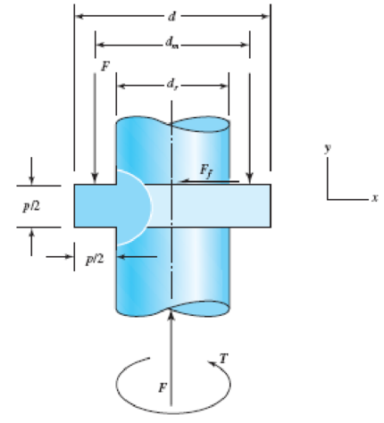
The figure shows a simple model of the loading of a square thread of a power screw transmitting an axial load F with an application of torque T . The torque is balanced by the frictional force F f acting along the top surface of the thread. The forces on the thread are considered to be distributed along the circumference of the mean diameter d m over the number of engaged threads, n t . From the figure, d m = d r + p /2, where d r is the root diameter of the thread and p is the pitch of the thread. ( a ) Considering the thread to be a cantilever beam as shown in the cutaway view, show that the nominal bending stress at the root of the thread can be approximated by σ b = ± 6 F π d r n t p ( b ) Show that the axial and maximum torsional shear stresses in the body of the shaft can be approximated by σ a = − 4 F π d r 2 and τ t = − 16 T π d r 3 ( c ) For the stresses of parts ( a ) and ( b ) show a three-dimensional representation of the state of stress on an element located at the intersection of the lower thread root base and the thread body. Using the given coordinate system label the stresses using the notation given in Fig. 3–8a. Problem 3–90 ( d ) A square-thread power screw has an outside diameter d = 1.5 in, pitch p = 0.25 in, and transmits a load F = 1 500 lbf through the application of a torque T = 235 lbf · in. If n t = 2, determine the key stresses and the corresponding principal stresses (normal and shear).
The figure shows a simple model of the loading of a square thread of a power screw transmitting an axial load F with an application of torque T . The torque is balanced by the frictional force F f acting along the top surface of the thread. The forces on the thread are considered to be distributed along the circumference of the mean diameter d m over the number of engaged threads, n t . From the figure, d m = d r + p /2, where d r is the root diameter of the thread and p is the pitch of the thread. ( a ) Considering the thread to be a cantilever beam as shown in the cutaway view, show that the nominal bending stress at the root of the thread can be approximated by σ b = ± 6 F π d r n t p ( b ) Show that the axial and maximum torsional shear stresses in the body of the shaft can be approximated by σ a = − 4 F π d r 2 and τ t = − 16 T π d r 3 ( c ) For the stresses of parts ( a ) and ( b ) show a three-dimensional representation of the state of stress on an element located at the intersection of the lower thread root base and the thread body. Using the given coordinate system label the stresses using the notation given in Fig. 3–8a. Problem 3–90 ( d ) A square-thread power screw has an outside diameter d = 1.5 in, pitch p = 0.25 in, and transmits a load F = 1 500 lbf through the application of a torque T = 235 lbf · in. If n t = 2, determine the key stresses and the corresponding principal stresses (normal and shear).
Solution Summary: The following diagram shows the loading of the square thread.
The figure shows a simple model of the loading of a square thread of a power screw transmitting an axial load F with an application of torque T. The torque is balanced by the frictional force Ff acting along the top surface of the thread. The forces on the thread are considered to be distributed along the circumference of the mean diameter dm over the number of engaged threads, nt. From the figure, dm = dr + p/2, where dr is the root diameter of the thread and p is the pitch of the thread.
(a) Considering the thread to be a cantilever beam as shown in the cutaway view, show that the nominal bending stress at the root of the thread can be approximated by
σ
b
=
±
6
F
π
d
r
n
t
p
(b) Show that the axial and maximum torsional shear stresses in the body of the shaft can be approximated by
σ
a
=
−
4
F
π
d
r
2
and
τ
t
=
−
16
T
π
d
r
3
(c) For the stresses of parts (a) and (b) show a three-dimensional representation of the state of stress on an element located at the intersection of the lower thread root base and the thread body. Using the given coordinate system label the stresses using the notation given in Fig. 3–8a.
Problem 3–90
(d) A square-thread power screw has an outside diameter d = 1.5 in, pitch p = 0.25 in, and transmits a load F = 1 500 lbf through the application of a torque T = 235 lbf · in. If nt = 2, determine the key stresses and the corresponding principal stresses (normal and shear).
The transmission shaft shown in the figure below is used by two V-belt pulleys for movement
transmission. Although the reliability of the system is required to be 0.95, the application coefficient
is 1.35, and the working life is 60000 hours, the transmission shaft rotates at a speed of 1250 rpm.
The direction and direction of application are the same and the Belt force on the loose arm of pulley
A is 1/3 of the Belt force on the stretched arm and make the most appropriate selection of ball
bearing bearings that can be used at points o and E from the tables provided in the appendix.
250
350
diameter 150
diameter 200
в
250 N
1350 N
After recording the applied twisting moment and resulted angle, fill the following
table
MT
(N.m)
T.
MPa
(degree)
(rad.)
Now, the twisting moment-twisting angle and shear stress-shear strain curves can
be plotted, then determine maximum shear stress, shear stress at proportional limit
and modulus of rigidity.
4-6 Problem
The following torsion test data were obtained for AA6061-T6 aluminum alloy has a
round cross section with 30mm outer diameter, 0 inner diameter and 100 length.
0 32
130
Twisted angle (): 0 1
Torque (N.m):
286
347 487
5.5
591
786
910
1105 1163 1235 1222
3.5
6.5
7.5
9.
10.5 13.5 16.5 21.5 25.5
> Plot the torque-twisted angle curve and determine the proportional limit on it.
Plot the shear stress-strain curve the determine the shearing strength and
modulus of rigidity.
Prof. Adnan N. Abood
Asst. Lec. Zainah Waheed
25
0:07I
| ZVAO
K/s a 15all KOREK
A locs.google.com
11
Q2: The extension spring shown
in the figure has full-twisted
loop ends. The material is AISI
1040Q&T 400FO wire. The
spring has 82 coils and is close-
wound with a preload of 18 Ibf.
(a) Find the closed length of the
spring.(b) Find the torsional
stress in the spring
corresponding to the preload.(c)
Estimate the spring rate.(d)
What load would cause
permanent deformation?(e)
What is the spring deflection
corresponding to the load found
?in part d
0.162 in
1 in
L-in R
-in R.
Option 1 O
Chapter 3 Solutions
Shigley's Mechanical Engineering Design (McGraw-Hill Series in Mechanical Engineering)
Need a deep-dive on the concept behind this application? Look no further. Learn more about this topic, mechanical-engineering and related others by exploring similar questions and additional content below.
BEARINGS BASICS and Bearing Life for Mechanical Design in 10 Minutes!; Author: Less Boring Lectures;https://www.youtube.com/watch?v=aU4CVZo3wgk;License: Standard Youtube License


 Mechanics of Materials (MindTap Course List)Mechanical EngineeringISBN:9781337093347Author:Barry J. Goodno, James M. GerePublisher:Cengage Learning