
Shigley's Mechanical Engineering Design (McGraw-Hill Series in Mechanical Engineering)
10th Edition
ISBN: 9780073398204
Author: Richard G Budynas, Keith J Nisbett
Publisher: McGraw-Hill Education
expand_more
expand_more
format_list_bulleted
Concept explainers
Videos
Textbook Question
Chapter 3, Problem 68P
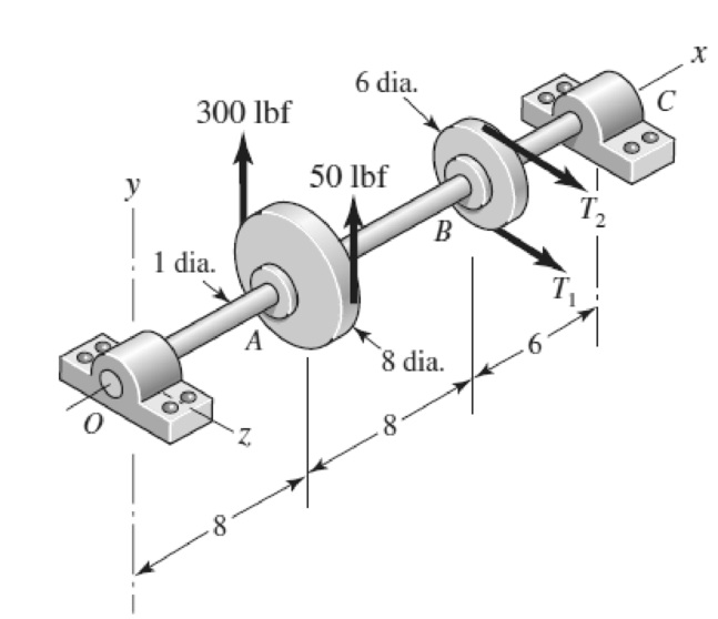
3-68* to 3-71* A countershaft two V-belt pulleys is shown in the figure. Pulley A receives power from a motor through a belt with the belt tensions shown. The power is transmitted through the shaft and delivered to the belt on pulley B. Assume the belt tension on the loose side at B is 15 percent of the tension on the tight side.
- (a) Determine the tensions in the belt on pulley B, assuming the shaft is running at a constant speed.
- (b) Find the magnitudes of the bearing reaction forces, assuming the bearings act as simple supports.
- (c) Draw shear-force and bending-moment diagrams for the shaft. If needed, make one set for the horizontal plane and another set for the vertical plane.
- (d) At the point of maximum bending moment, determine the bending stress and the torsional shear stress.
- (e) At the point of maximum bending moment, determine the principal stresses and the maximum shear stress.
Problem 3-70*
Dimensions in inches.
Expert Solution & Answer

Trending nowThis is a popular solution!

Students have asked these similar questions
2. A countershaft carrying two V-belt pulleys is shown in the figure. Pulley A receives power from a
motor through a belt with the belt tensions shown. The power is transmitted through the shaft and
delivered to the belt on pulley B. Assume the belt tension on the loose side at B is 15 percent of the
tension on the tight side.
a. Determine the tensions in the belt on pulley B,
10 in
assuming the shaft is running at a constant
speed.
18 in
b. Find the magnitudes of the bearing reaction
forces, assuming the bearings act as simple
12 in
supports.
T2
C.
Derive the load intensity function (q), shear force
500 lbf
(V) and bending moment (M) relations by using
75 lbf
the Singularity Functions.
8-in dia.
В
d. Draw shear-force and bending-moment
1--in dia.
diagrams for the shaft.
10-in dia.
A countershaft carrying two V-belt pulleys is shown in the figure. Pulley A receives power from a motor through a belt with the belt tensions shown. The power is transmitted through the shaft and delivered to the belt on pulley B. Assume the belt tension on the loose side at B is 15 percent of the tension on the tight side.
Determine the tensions in the belt on pulley B, assuming the shaft is running at a constant speed.
Find the magnitudes of the bearing reaction forces, assuming the bearings act as simple supports.
Draw shear-force and bending-moment diagrams for the shaft. If needed, make one set for the horizontal plane and another set for the vertical plane.
At the point of maximum bending moment, determine the bending stress and the torsional shear stress.
At the point of maximum bending moment, determine the principal stresses and the maximum shear stress.
A countershaft carrying two V-belt pulley is shown in Figure 1. Pulley A receivespower from a motor through a belt with the belt tensions shown. The power is transmittedthrough the shaft and delivered to the belt on Pulley B. Assume the belt tension on the loose sideat B is 15 percent of the tension on the tight side.(a) Determine the tensions in the belt on pulley B (assuming the shaft is running at a constantspeed).(b) Find the magnitudes of the bearing reaction forces assuming the bearings act as simplesupports.(c) Draw the shear force and bending moment diagrams for the shaft.
Chapter 3 Solutions
Shigley's Mechanical Engineering Design (McGraw-Hill Series in Mechanical Engineering)
Ch. 3 - 31 to 34 Sketch a free-body diagram of each...Ch. 3 - 31 to 34 Sketch a free-body diagram of each...Ch. 3 - Sketch a free-body diagram of each element in the...Ch. 3 - 3-1 to 3-4 Sketch a free-body diagram of each...Ch. 3 - 35 to 38 For the beam shown, find the reactions at...Ch. 3 - 35 to 38 For the beam shown, find the reactions at...Ch. 3 - 35 to 38 For the beam shown, find the reactions at...Ch. 3 - For the beam shown, find the reactions at the...Ch. 3 - For the beam shown, find the reactions at the...Ch. 3 - Repeat Prob. 36 using singularity functions...
Ch. 3 - Repeat Prob. 37 using singularity functions...Ch. 3 - Repeat Prob. 38 using singularity functions...Ch. 3 - For a beam from Table A9, as specified by your...Ch. 3 - A beam carrying a uniform load is simply supported...Ch. 3 - For each of the plane stress states listed below,...Ch. 3 - Repeat Prob. 315 for: (a)x = 28 MPa, y = 7 MPa, xy...Ch. 3 - Repeat Prob. 315 for: a) x = 12 kpsi, y = 6 kpsi,...Ch. 3 - For each of the stress states listed below, find...Ch. 3 - Repeat Prob. 318 for: (a)x = 10 kpsi, y = 4 kpsi...Ch. 3 - The state of stress at a point is x = 6, y = 18, z...Ch. 3 - The state of stress at a point is x = 6, y = 18, z...Ch. 3 - Repeat Prob. 320 with x = 10, y = 40, z = 40, xy =...Ch. 3 - A 34-in-diameter steel tension rod is 5 ft long...Ch. 3 - Repeat Prob. 323 except change the rod to aluminum...Ch. 3 - A 30-mm-diameter copper rod is 1 m long with a...Ch. 3 - A diagonal aluminum alloy tension rod of diameter...Ch. 3 - Repeat Prob. 326 with d = 16 mm, l = 3 m, and...Ch. 3 - Repeat Prob. 326 with d = 58 in, l = 10 ft, and...Ch. 3 - Electrical strain gauges were applied to a notched...Ch. 3 - Repeat Prob. 329 for a material of aluminum. 3-29...Ch. 3 - The Roman method for addressing uncertainty in...Ch. 3 - Using our experience with concentrated loading on...Ch. 3 - The Chicago North Shore Milwaukee Railroad was an...Ch. 3 - For each section illustrated, find the second...Ch. 3 - 3-35 to 3-38 For the beam illustrated in the...Ch. 3 - 3-35 to 3-38 For the beam illustrated in the...Ch. 3 - 3-35 to 3-38 For the beam illustrated in the...Ch. 3 - 3-35 to 3-38 For the beam illustrated in the...Ch. 3 - The figure illustrates a number of beam sections....Ch. 3 - A pin in a knuckle joint canning a tensile load F...Ch. 3 - Repeat Prob. 3-40 for a = 6 mm, b = 18 mm. d = 12...Ch. 3 - For the knuckle joint described in Prob. 3-40,...Ch. 3 - The figure illustrates a pin tightly fitted into a...Ch. 3 - For the beam shown, determine (a) the maximum...Ch. 3 - A cantilever beam with a 1-in-diameter round cross...Ch. 3 - Consider a simply supported beam of rectangular...Ch. 3 - In Prob. 346, h 0 as x 0, which cannot occur. If...Ch. 3 - 348 and 349 The beam shown is loaded in the xy and...Ch. 3 - The beam shown is loaded in the xy and xz planes....Ch. 3 - Two steel thin-wall tubes in torsion of equal...Ch. 3 - Consider a 1-in-square steel thin-walled tube...Ch. 3 - The thin-walled open cross-section shown is...Ch. 3 - 3-53 to 3-55 Using the results from Prob. 3-52,...Ch. 3 - 3-53 to 3-55 Using the results from Prob. 3-52,...Ch. 3 - 3-53 to 3-55 Using the results from Prob. 3-52,...Ch. 3 - Two 300-mm-long rectangular steel strips are...Ch. 3 - Using a maximum allowable shear stress of 70 Mpa,...Ch. 3 - Repeat Prob. 357 with an allowable shear stress of...Ch. 3 - Using an allowable shear stress of 50 MPa,...Ch. 3 - A 20-mm-diameter steel bar is to be used as a...Ch. 3 - A 2-ft-long steel bar with a 34-in diameter is to...Ch. 3 - A 40-mm-diameter solid steel shaft, used as a...Ch. 3 - Generalize Prob. 3-62 for a solid shaft of...Ch. 3 - A hollow steel shaft is to transmit 4200 N m of...Ch. 3 - The figure shows an endless-bell conveyor drive...Ch. 3 - The conveyer drive roll in the figure for Prob....Ch. 3 - Consider two shafts in torsion, each of the same...Ch. 3 - 3-68 to 3-71 A countershaft two V-belt pulleys is...Ch. 3 - 3-68 to 3-71 A countershaft two V-belt pulleys is...Ch. 3 - 3-68 to 3-71 A countershaft two V-belt pulleys is...Ch. 3 - A countershaft carrying two V-belt pulleys is...Ch. 3 - A gear reduction unit uses the countershaft shown...Ch. 3 - Prob. 73PCh. 3 - Prob. 74PCh. 3 - Prob. 75PCh. 3 - Prob. 76PCh. 3 - Prob. 77PCh. 3 - Prob. 78PCh. 3 - Prob. 79PCh. 3 - The cantilevered bar in the figure is made from a...Ch. 3 - Repeat Prob. 3-80 with Fx = 0, Fy = 175 lbf, and...Ch. 3 - Repeat Prob. 3-80 with Fx = 75 lbf, Fy= 200 lbf,...Ch. 3 - For the handle in Prob. 3-80, one potential...Ch. 3 - The cantilevered bar in the figure is made from a...Ch. 3 - Repeat Prob. 3-84 with Fx = 300 lbf, Fy = 250 lbf,...Ch. 3 - Repeat Prob. 3-84 with Fx = 300 lbf, Fy = 250 lbf,...Ch. 3 - Repeat Prob. 3-84 for a brittle material,...Ch. 3 - Repeat Prob. 3-84 with Fx = 300 lbf, Fy = 250 lbf,...Ch. 3 - Repeat Prob. 3-84 with Fx = 300 lbf, Fy = 250 lbf,...Ch. 3 - The figure shows a simple model of the loading of...Ch. 3 - Develop the formulas for the maximum radial and...Ch. 3 - Repeat Prob. 391 where the cylinder is subject to...Ch. 3 - Develop the equations for the principal stresses...Ch. 3 - 3-94 to 3-96 A pressure cylinder has an outer...Ch. 3 - 3-94 to 3-96 A pressure cylinder has an outer...Ch. 3 - 3-94 to 3-96A pressure cylinder has an outer...Ch. 3 - 3-97 to 3-99 A pressure cylinder has an outer...Ch. 3 - 3-97 to 3-99 A pressure cylinder has an outer...Ch. 3 - 3-97 to 3-99 A pressure cylinder has an outer...Ch. 3 - An AISI 1040 cold-drawn steel tube has an OD = 50...Ch. 3 - Repeat Prob. 3-100 with an OD of 2 in and wall...Ch. 3 - Prob. 102PCh. 3 - Prob. 103PCh. 3 - A thin-walled cylindrical Steel water storage tank...Ch. 3 - Repeat Prob. 3-104 with the tank being pressurized...Ch. 3 - Find the maximum shear stress in a 512-in-diameter...Ch. 3 - The maximum recommended speed for a...Ch. 3 - An abrasive cutoff wheel has a diameter of 5 in,...Ch. 3 - A rotary lawnmower blade rotates at 3500 rev/min....Ch. 3 - 3110 to 3115 The table lists the maximum and...Ch. 3 - Prob. 111PCh. 3 - Prob. 112PCh. 3 - 3110 to 3115 The table lists the maximum and...Ch. 3 - Prob. 114PCh. 3 - Prob. 115PCh. 3 - 3116 to 3119 The table gives data concerning the...Ch. 3 - Prob. 117PCh. 3 - Prob. 118PCh. 3 - 3116 to 3119 The table gives data concerning the...Ch. 3 - A utility hook was formed from a round rod of...Ch. 3 - A utility hook was formed from a round rod of...Ch. 3 - The steel eyebolt shown in the figure is loaded...Ch. 3 - For Prob. 3122 estimate the stresses at the inner...Ch. 3 - Repeat Prob. 3122 with d = 14 in, Ri = 12 in, and...Ch. 3 - Repeat Prob. 3123 with d = 14 in, Ri = 12 in, and...Ch. 3 - Shown in the figure is a 12-gauge (0.1094-in) by...Ch. 3 - Repeat Prob. 3126 with a 10-gauge (0.1406-in)...Ch. 3 - Prob. 128PCh. 3 - The cast-iron bell-crank lever depicted in the...Ch. 3 - Prob. 130PCh. 3 - Prob. 131PCh. 3 - A cast-steel C frame as shown in the figure has a...Ch. 3 - Two carbon steel balls, each 30 mm in diameter,...Ch. 3 - A carbon steel ball with 25-mm diameter is pressed...Ch. 3 - Repeat Prob. 3134 but determine the maximum shear...Ch. 3 - A carbon steel ball with a 30-mm diameter is...Ch. 3 - An AISI 1018 steel ball with 1-in diameter is used...Ch. 3 - An aluminum alloy cylindrical roller with diameter...Ch. 3 - A pair of mating steel spur gears with a 0.75-in...Ch. 3 - 3140 to 3142 A wheel of diameter d and width w...Ch. 3 - 3140 to 3142 A wheel of diameter d and width w...Ch. 3 - 3140 to 3142 A wheel of diameter d and width w...
Knowledge Booster


Learn more about
Need a deep-dive on the concept behind this application? Look no further. Learn more about this topic, mechanical-engineering and related others by exploring similar questions and additional content below.Similar questions
- Repeat Problem 6.4-14 but use the configuration of channel shapes and loading shown in the figure. Use P = 250 N.arrow_forwardSolve the preceding problem for the following data:P = 160 kN,JV = 200 tN,L = 2 m,b = 95 mm, h = 300 mm, and d = 200 mmarrow_forwardA cable and pulley system in the figure part a supports a cage of a mass 300 kg at B. Assume that this includes the mass of the cables as well. The thickness or each of the three steel pulleys is t = 40 mm. The pin diameters are dPA= 25 mm, dB= 30 mm. and dc= 22 mm (see figure part a and part b). (a) Find expressions for the resultant forces acting on the pulleys at A, B. and C in terms of cubic tension T. (b) What is the maximum weight W that can be added to the cage at B based on the following allowable stresses? Shear stress in the pins is 50 MPa; bearing stress between the pin and the pulley is 110 MPa.arrow_forward
- Pipe 2 has been inserted snugly into Pipe I. but the holes Tor a connecting pin do not line up; there is a gap s. The user decides to apply either force P:lo Pipe I or force P-, to Pipe 2, whichever is smaller. Determine the following using the numerical properties in the box. (a) If only P{is applied, find Pt{tips} required to close gap s; if a pin is then inserted and Ptremoved, what are reaction forces RAand RBfor this load case? (b) If only P2is applied, find P2{kips) required to close gap a; if a pin is inserted and P2removed, what are reaction forces R^ and RBfor this load case? (c) What is the maximum shear stress in the pipes, for the loads in parts (a) and (b)? (d) If a temperature increase IT is to be applied to the entire structure to close gaps{instead of applying forces Ptand P2), find the AT required to close the gap. If a pin is inserted after the gaphas closed, what are reaction forces .''.', and RBfor this case? (e) Finally, if the structure (with pin inserted) then cools to the original ambient temperature, what are reaction forces Rtand Parrow_forwardThe inclined beam represents a ladder with the Following applied loads: the weight (W) of the house painter and the distributed weight (u) of the ladder itself. Find support reactions at A and B: then plot axial force (N), shear (V), and moment (M) diagrams. Label all critical N, V, and M values and also the distance to points where any critical ordmates are zero. Plot N, V, and M diagrams normal to the inclined ladder. Repeat part (a) for the case of the ladder suspended from a pin at B and traveling on a roller support perpendicular to the floor at A.arrow_forwardA magnesium-alloy wire of diameter d = 4mm and length L rotates inside a flexible tube in order to open or close a switch from a remote location (see figure). A torque Tis applied manually (either clockwise or counterclockwise) at end 5, thus twisting the wire inside the tube. At the other end A, the rotation of the wire operates a handle that opens or closes the switch. A torque T0 = 0.2 N · m is required to operate the switch. The torsional stiffness of the tube, combined with friction between the tube and the wire, induces a distributed torque of constant intensity t = 0.04N m/m (torque per unit distance) acting along the entire length of the wire. (a) If the allowable shear stress in the wire is T allow = 30 MPa, what is the longest permissible length Lmaxof the wire?arrow_forward
arrow_back_ios
SEE MORE QUESTIONS
arrow_forward_ios
Recommended textbooks for you
 Mechanics of Materials (MindTap Course List)Mechanical EngineeringISBN:9781337093347Author:Barry J. Goodno, James M. GerePublisher:Cengage Learning
Mechanics of Materials (MindTap Course List)
Mechanical Engineering
ISBN:9781337093347
Author:Barry J. Goodno, James M. Gere
Publisher:Cengage Learning
Understanding Torsion; Author: The Efficient Engineer;https://www.youtube.com/watch?v=1YTKedLQOa0;License: Standard YouTube License, CC-BY