
Concept explainers
Videos
For the problem specified in the table, build upon the results of the original problem to determine the minimum factor of safety for yielding. Use both the maximum-shear-stress theory and the distortion-energy theory, and compare the results. The material is 1018 CD steel.


3–79* Repeat Prob. 3–77 with T = 900 lbf · in, a = 6 in, b = 5 in, c = 10 in, d = 1.375 in, e = 4 in, f = 10 in, and g = 6 in.
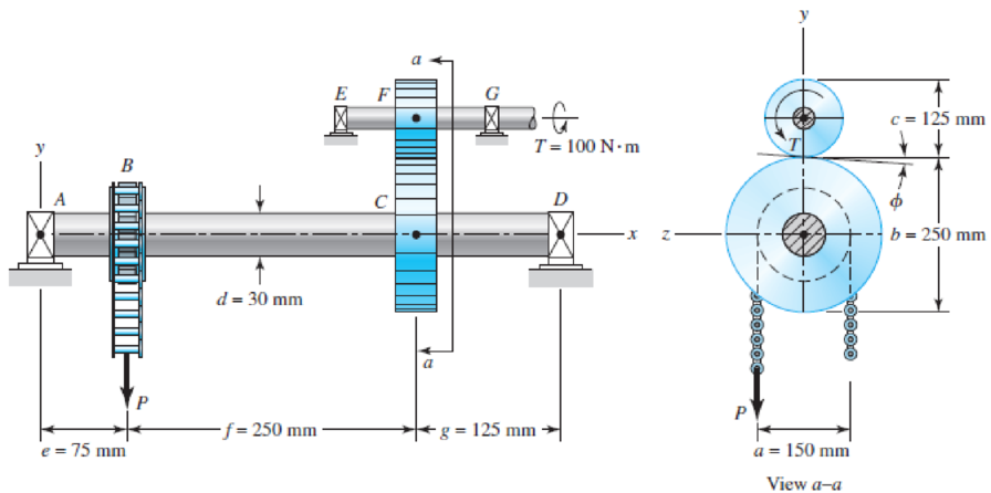
3–77* A torque T = 100 N · m is applied to the shaft EFG, which is running at constant speed and contains gear F. Gear F transmits torque to shaft ABCD through gear C, which drives the chain sprocket at B, transmitting a force P as shown. Sprocket B, gear C, and gear F have pitch diameters of a = 150, b = 250, and c = 125 mm, respectively. The contact force between the gears is transmitted through the pressure angle ϕ = 20°. Assuming no frictional losses and considering the bearings at A, D, E, and G to be simple supports, locate the point on shaft ABCD that contains the maximum tensile bending and maximum torsional shear stresses. Combine these stresses and determine the maximum principal normal and shear stresses in the shaft.
Want to see the full answer?
Check out a sample textbook solution
Chapter 5 Solutions
Shigley's Mechanical Engineering Design (McGraw-Hill Series in Mechanical Engineering)


- Solve the preceding problem if the thickness of the steel plate is. t = 12 mm. the gage readings are x = 530 × 10-6 (elongation) and y = -210 -× l0-6 (shortening), the modulus is E = 200 GPa, and Poisson’s ratio is v = 0.30.arrow_forwardTwo sections of steel drill pipe, joined by bolted flange plates at Ä are being tested to assess the adequacy of both the pipes. In the test, the pipe structure is fixed at A, a concentrated torque of 500 kN - m is applied at x = 0.5 m, and uniformly distributed torque intensity t1= 250 kN m/m is applied on pipe BC. Both pipes have the same inner diameter = 200 mm. Pipe AB has thickness tAB=15 mm, while pipe BC has thickness TBC= 12 mm. Find the maximum shear stress and maximum twist of the pipe and their locations along the pipe. Assume G = 75 GPa.arrow_forwardThe strength-to-weight ratio of a structural material is defined as its load-carrying capacity divided by its weight. For materials in tension, use a characteristic tensile stress obtained from a stress-strain curve as a measure of strength. For instance, either the yield stress or the ultimate stress could be used, depending upon the particular application. Thus, the strength-to-weight ratio RS/Wfor a material in tension is defined as Rs/w= in which a is the characteristic stress and 7 is the weight density. Note that the ratio has units of length. Using the ultimate stress Uas the strength parameter, calculate the strength-to-weight ratio (in units of meters) for each of the following materials: aluminum alloy 606I-T6, Douglas fir (in bending}, nylon. structural steel ASTM-A57.2, and a titanium alloy. Obtain the material properties from Tables [-1 and 1-3 of Appendix I. When a range of values is given in a table, use the average value.arrow_forward
- A pressure vessel is exposed to a combination of loads as shown below. The vessel (diameter 100 mm) has a wall thickness of 3 mm. Address the following: (a) If the yield strength of the material is 144 MPa, determine the largest tension force P with respect to a factor of safety of 2 applied to the distortional energy theory. (b) If the applied torque and tension load were removed, determine the minimum wall thickness using a factor of safety of 1.75 with respect to the distortional energy theory. Illustrate you results using an appropriate yield envelope. p = 3.5 MPa T = 450 N-m P Tarrow_forwardA ductile hot-rolled steel bar has a minimum yield strength in tension and compression of 350 MPa. Using the distortion-energy and maximum-shear-stress theories, analyze the following plane stress states/principal stresses. 10 kpsi | (1) OA = -50 kpsi, oß =arrow_forward2. The following handle is loaded at points B and C, as shown below. 0.8 m 40 mm 0.4 m If the force P = 20F, and the material of the handle has Sy = 250 MPa: a. Show the stress state at element A. b. Using the distortion energy theory, find the maximum force F that guarantees a safety factor of 1.4.arrow_forward
- 1. We can visualize the factor of safety for an arbitrary stress using a surface in principal stress space. For a ductile material that yields according to a von Mises criterion with a yield stress σy, sketch the von Mises surface in σ₁ - 02 space and sketch the stress surface that corresponds to a factor of safety FoS = 2. For a brittle material that yields according to a max normal (Rankine) criterion with a tensile strength Gyt and a compressive strength σvc = 20yt, sketch the yield surface and the surface that corresponds to a factor of safety FoS = 2.arrow_forwardConsider a machine element as shown in the figure. The stress element at a critical point on this element is shown. Determine the smallest yield stress for a steel that can be selected for the member, based on the maximum-shear-stress theory. What result you expect if maximum distortion energy theory is used. 80ksi 25 ksiarrow_forward2. Consider a bar of AISI 1015 cold-drawn steel. Using the distortion-energy and maximum-shear-stress theories to determine the factors of safety for a stress state with the following plane principal stresses: 04 = 30 kpsi, OB = 15 kpsi.arrow_forward
- Problem 1: The stress state at a critical point on a steel part (Sy = 250 MPa) is shown below. Determine whether yielding occurs according to the Maximum Distortional Energy (Von Mises) failure theory. 60 MPa 40 MPa 70 MPaarrow_forwardThis problem illustrates that the factor of safety for a machine element depends on the particular point selected for analysis. Here you are to compute factors of safety, based upon the distortion-energy theory, for stress elements at A and B of the member shown in the figure. This bar is made of AISI 1006 cold-drawn steel and is loaded by the forces F = 0.55 kN, P = 8.0 kN, and T = 30 N m = 280 MPa 100 mm A B d=20 mmarrow_forwardOn the figure shown, a ring which is supported by the spring, is subjected to a concurrent forces P1 = 2000 N, and P2 = 2500 N. The ring is being kept in an equilibrium state by the spring attached. Determine the shearing stress of the spring (using the first equation) if the mean radius is 100 mm, G = 30 GPa, number of turns is 10, and diameter of the spring is 10 mm. Also, determine the deformation of the spring.Show complete solution with FBDarrow_forward
 Mechanics of Materials (MindTap Course List)Mechanical EngineeringISBN:9781337093347Author:Barry J. Goodno, James M. GerePublisher:Cengage Learning