
Concept explainers
Videos
5-39* to 5-55* For the problem specified in the table, build upon the results of the original problem to determine the minimum factor of safety for yielding. Use both the maximum-shear-stress theory and the distortion-energy theory, and compare the results. The material is 1018 CD steel.
| Problem Number | Original Problem, Page Number |
| 5-52* | 3-83, 154 |
3-83* For the handle in Prob. 3-80, one potential failure mode is twisting of the flat plate BC. Determine the maximum value of the shear stress due to torsion in the main section of the plate, ignoring the complexities of the interfaces at B and C.
3-80* The cantilevered bar in the figure is made from a ductile material and is statically loaded with Fy = 200 lbf and Fx = Fz = 0. Analyze the stress situation in rod AB by obtaining the following information.
- (a) Determine the precise location of the critical stress element.
- (b) Sketch the critical stress element and determine magnitudes and directions for all stresses acting on it. (Transverse shear may only be neglected if you can justify this decision.)
- (c) For the critical stress dement, determine the principal stresses and the maximum shear stress.
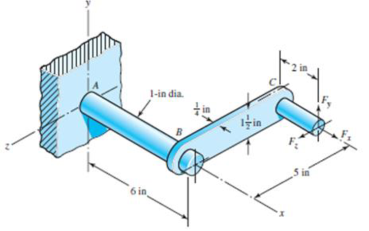
Problem 3-80*
Want to see the full answer?
Check out a sample textbook solution
Chapter 5 Solutions
Shigley's Mechanical Engineering Design (McGraw-Hill Series in Mechanical Engineering)


- A polyethylene tube (length L) has a cap that when installed compresses a spring (with under-formed length L1) by an amount ?? = (L1 = L). Ignore deformations of the cap and base. Use the force at the base of the spring as the redundant. Use numerical properties given in the boxes. (a) What is the resulting Force-in the spring, Fk? (b) What is the resulting Force in the tube, Ftl (c) What is the filial length of the tube, Lf? (d) What temperature change ?T inside the tube will result in zero force in the springarrow_forwardThe rotating shaft shown in the figure is machined from AISI 1020 CD steel. It is subjected to a force of F = 6 kN. Find the minimum factor of safety for fatigue based on infinite life. If the life is not infinite, estimate the number of cycles. Be sure to check for yielding. The diameter of the bar is 35 mm and the radius of the step down in the shaft is 3 mm. All dimensions listed below are in mm. 25 D. 20 - 20 -35 D. 180 -3 R. 500- F 280- -175- -50 D. -25 D. -20 20arrow_forward6-28 The figure shows a formed round-wire cantilever spring subjected to a varying force. The hardness tests made on 50 springs gave a minimum hardness of 400 Brinell. It is apparent from the mounting details that there is no stress concentration. A visual inspection of the springs indicates that the surface finish corresponds closely to a hot- rolled finish. Ignore curvature effects on the bending stress. What number of applica- tions is likely to cause failure? Solve using: (a) Goodman criterion. (b) Gerber criterion. = 40 lbf max 12 in- = 20 lbf min Problem 6-28arrow_forward
- Required information This problem illustrates that the factor of safety for a machine element depends on the particular point selected for analysis. Here you are to compute factors of safety, based upon the distortion-energy theory, for stress elements at A and B of the member shown in the figure. This bar is made of AISI 1006 cold-drawn steel and is loaded by the forces F= 0.55 kN, P= 4 kN, and T=25 N-m. Given: Sy= 280 MPa. NOTE: This is a multi-part question. Once an answer is submitted, you will be unable to return to this part. B 15-mm D. -100 mm What is the value of the axial stress at point A? The value of the axial stress at point A is MPa.arrow_forward6-25 The cold-drawn AISI 1040 steel bar shown in the figure reversed axial load fluctuating between 28 kN in compression to 28 kN in tension. Estimate the fatigue factor of safety based on achieving infinite life and the yielding factor of safety. If infinite life is not predicted, estimate the number of cycles to failure. 6-mm D. 25 mm Problem 6-25 10 mmarrow_forwardAfter recording the applied twisting moment and resulted angle, fill the following table MT (N.m) T. MPa (degree) (rad.) Now, the twisting moment-twisting angle and shear stress-shear strain curves can be plotted, then determine maximum shear stress, shear stress at proportional limit and modulus of rigidity. 4-6 Problem The following torsion test data were obtained for AA6061-T6 aluminum alloy has a round cross section with 30mm outer diameter, 0 inner diameter and 100 length. 0 32 130 Twisted angle (): 0 1 Torque (N.m): 286 347 487 5.5 591 786 910 1105 1163 1235 1222 3.5 6.5 7.5 9. 10.5 13.5 16.5 21.5 25.5 > Plot the torque-twisted angle curve and determine the proportional limit on it. Plot the shear stress-strain curve the determine the shearing strength and modulus of rigidity. Prof. Adnan N. Abood Asst. Lec. Zainah Waheed 25arrow_forward
- This problem illustrates that the factor of safety for a machine element depends on the particular point selected for analysis. Here you are to compute factors of safety, based upon the distortion-energy theory, for stress elements at A and B of the member shown in the figure. This bar is made of AISI 1006 cold-drawn steel and is loaded by the forces F = 0.55 kN, P = 8.0 kN, and T = 30 N m = 280 MPa 100 mm A B d=20 mmarrow_forwarda) The rotating step shaft is subjected to the force as shown in the figure. It is supported by bearings at A and F. The shaft is machined using AISI 1040 CD steel. Determine the minimum fatigue factor of safety based on achieving infinite life. If infinite life is not predicted, estimate the number of cycles failure. Also check for yielding. Given Data: (Notch sensitivity (q)=0.8, Sut=85 kpsi, Syield= 71 kpsi, Surface condition modification factor ka=0.879, Size modification factor kb=0.790, Load modification factor kc=1, fatigue fraction (f)=0.867) * In order to determine Kt; Use Figure A-15-9 in your textbook. Dimensions are in inch and all fillet radius:1/14 inch y 860 lbf de 1.75 1.5 1.0 1.0 B V A| D E F 0.5 8 -8.5- R1 R2 -19.5 20arrow_forward2. The rotating shaft shown in the figure is machined from AISI 1020 CD steel. It is subjected to a force of F= 5.7 kN. Find the minimum factor of safety for fatigue based on infinite life. If the life is not infinite, estimate the number of cycles. Be sure to check for yielding. 25 D.- 20- -20 -35 D. -180- -500- -3 R. 280- (units in mm) -175- -50 D. -25 D. -20 -20arrow_forward
- The figure shows a shaft mounted in bearings at A and D and having pulleys at B and C. The forces shown acting on the pulley surfaces represent the belt tensions. The shaft is to be made of AISI 1035 CD steel. The shaft is rotating at speed of 1000 rpm. Find the minimum factor of safety for fatigue based on infinite life. If the life is not infinite, estimate the number of cycles. Be sure to check for yielding. Take shaft diameter to be 1.5 inches.arrow_forwardQ-3 A 25-mm-diameter solid round bar has a groove 2.5-mm deep with a 2.5-mm radius machined into it. The bar is made of AISI 1050 CD steel and is subjected to a purely reversing torque of 250 N-m. For the S-N curve of this material, let f = 0.9. (a) Estimate the number of cycles to failure. (b) If the bar is also placed in an environment with a temperature of 400°C, estimate the number of cycles to failure.arrow_forwardpls find box ur answer Determine the value of the von Mises stress at point A. The von Mises stress at point A is This problem illustrates that the factor of safety for a machine element depends on the particular point selected for analysis. Here you are to compute factors of safety, based upon the distortion-energy theory, for stress elements at A and B of the member shown in the figure. This bar is made of AISI 1006 cold- drawn steel and is loaded by the forces F= 0.55 kN, P = 4 kN, and T = 25 N-m. Given: Sy= 280 MPa. 5 15-mm D. 100 mm- MPa.arrow_forward
 Mechanics of Materials (MindTap Course List)Mechanical EngineeringISBN:9781337093347Author:Barry J. Goodno, James M. GerePublisher:Cengage Learning