
Shigley's Mechanical Engineering Design (McGraw-Hill Series in Mechanical Engineering)
10th Edition
ISBN: 9780073398204
Author: Richard G Budynas, Keith J Nisbett
Publisher: McGraw-Hill Education
expand_more
expand_more
format_list_bulleted
Concept explainers
Videos
Textbook Question
Chapter 6, Problem 16P
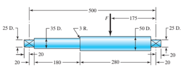
The rotating shaft shown in the figure is machined from AISI 1020 CD steel. It is subjected to a force of F = 6 kN. Find the minimum factor of safety for fatigue based on infinite life. If the life is not infinite, estimate the number of cycles. Be sure to check for yielding.
Problem 6-16 Dimensions in millimeters
Expert Solution & Answer
Want to see the full answer?
Check out a sample textbook solution
Students have asked these similar questions
6-28 The figure shows a formed round-wire cantilever spring subjected to a varying force.
The hardness tests made on 50 springs gave a minimum hardness of 400 Brinell. It is
apparent from the mounting details that there is no stress concentration. A visual
inspection of the springs indicates that the surface finish corresponds closely to a hot-
rolled finish. Ignore curvature effects on the bending stress. What number of applica-
tions is likely to cause failure? Solve using:
(a) Goodman criterion.
(b) Gerber criterion.
= 40 lbf
max
12 in-
= 20 lbf
min
Problem 6-28
The rotating shaft shown in the figure is machined from AISI 1020 CD steel. It is subjected to a force of F = 6 kN. Find the
minimum factor of safety for fatigue based on infinite life. If the life is not infinite, estimate the number of cycles. Be
sure to check for yielding. The diameter of the bar is 35 mm and the radius of the step down in the shaft is 3 mm. All
dimensions listed below are in mm.
25 D.
20
- 20
-35 D.
180
-3 R.
500-
F
280-
-175-
-50 D.
-25 D.
-20
20
A non-rotating shaft shown in the figure is machined from ASTM 30 Cast iron. It is subjected to a forceof ? = 5kN. Find the minimum factor of safety using Modified-Mohr theory. All dimensions are in mm
Chapter 6 Solutions
Shigley's Mechanical Engineering Design (McGraw-Hill Series in Mechanical Engineering)
Ch. 6 - A 10-mm steel drill rod was heat-treated and...Ch. 6 - Prob. 2PCh. 6 - A steel rotating-beam test specimen has an...Ch. 6 - A steel rotating-beam test specimen has an...Ch. 6 - A steel rotating-beam test specimen has an...Ch. 6 - Repeat Prob. 6-5 with the specimen having an...Ch. 6 - A steel rotating-beam test specimen has an...Ch. 6 - Derive Eq. (6-17). Rearrange the equation to solve...Ch. 6 - For the interval 103 N 106 cycles, develop an...Ch. 6 - Estimate the endurance strength of a...
Ch. 6 - Two steels are being considered for manufacture of...Ch. 6 - A 1-in-diamctcr solid round bar has a groove...Ch. 6 - A solid square rod is cantilevered at one end. The...Ch. 6 - A rectangular bar is cut from an AISI 1020...Ch. 6 - A solid round bar with diameter of 2 in has a...Ch. 6 - The rotating shaft shown in the figure is machined...Ch. 6 - The shaft shown in the figure is machined from...Ch. 6 - Solve Prob. 6-17 except with forces F1 = 1200 lbf...Ch. 6 - Bearing reactions R1 and R2 are exerted on the...Ch. 6 - A bar of steel has the minimum properties Se = 40...Ch. 6 - Repeat Prob. 6-20 but with a steady torsional...Ch. 6 - Repeat Prob. 6-20 but with a steady torsional...Ch. 6 - Repeat Prob. 6-20 but with an alternating...Ch. 6 - A bar of steel has the minimum properties Se = 40...Ch. 6 - The cold-drawn AISI KUO steel bar shown in the...Ch. 6 - Repeat Prob. 6-25 for a load that fluctuates from...Ch. 6 - An M14 2 hex-head bolt with a nut is used to...Ch. 6 - The figure shows a formed round-wire cantilever...Ch. 6 - The figure is a drawing of a 4- by 20-mm latching...Ch. 6 - The figure shows the free-body diagram of a...Ch. 6 - Solve Prob. 6-30 except let w1 = 2.5 in. w2 = l.5...Ch. 6 - For the part in Prob. 630, recommend a fillet...Ch. 6 - Prob. 33PCh. 6 - Prob. 34PCh. 6 - A part is loaded with a combination of bending,...Ch. 6 - Repeat the requirements of Prob. 6-35 with the...Ch. 6 - 6-37 to 6-46For the problem specified in the build...Ch. 6 - 6-37 to 6-46For the problem specified in the build...Ch. 6 - 637 to 646 For the problem specified in the table,...Ch. 6 - For the problem specified in the table, build upon...Ch. 6 - 6-37 to 6-46 For the problem specified in the...Ch. 6 - 6-37 to 6-46 For the problem specified in the...Ch. 6 - 6-37 to 6-46 For the problem specified in the...Ch. 6 - Problem Number Original Problem, Page Number 637...Ch. 6 - 6-37 to 6-46 For the problem specified in the...Ch. 6 - 6-37 to 6-46 For the problem specified in the...Ch. 6 - 6-47 to 6-50 For the problem specified in the...Ch. 6 - 6-47 to 6-50 For the problem specified in the...Ch. 6 - Prob. 49PCh. 6 - Prob. 50PCh. 6 - 6-51 to 6-53 For the problem specified in the...Ch. 6 - 6-51 to 6-53 For the problem specified in the...Ch. 6 - 6-51 to 6-53 For the problem specified in the...Ch. 6 - Solve Prob. 6-17 except include a steady torque of...Ch. 6 - Solve Prob. 618 except include a steady torque of...Ch. 6 - In the figure shown, shaft A, made of AISI 1020...Ch. 6 - A schematic of a clutch-testing machine is shown....Ch. 6 - For the clutch of Prob. 657, the external load P...Ch. 6 - A flat leaf spring has fluctuating stress of max =...Ch. 6 - A rotating-beam specimen with an endurance limit...Ch. 6 - A machine part will be cycled at 350 MPa for 5...Ch. 6 - The material properties of a machine part are Sut...Ch. 6 - Repeat Prob. 662 using the Goodman criterion....
Knowledge Booster


Learn more about
Need a deep-dive on the concept behind this application? Look no further. Learn more about this topic, mechanical-engineering and related others by exploring similar questions and additional content below.Similar questions
- a) The rotating step shaft is subjected to the force as shown in the figure. It is supported by bearings at A and F. The shaft is machined using AISI 1040 CD steel. Determine the minimum fatigue factor of safety based on achieving infinite life. If infinite life is not predicted, estimate the number of cycles failure. Also check for yielding. Given Data: (Notch sensitivity (q)=0.8, Sut=85 kpsi, Syield= 71 kpsi, Surface condition modification factor ka=0.879, Size modification factor kb=0.790, Load modification factor kc=1, fatigue fraction (f)=0.867) * In order to determine Kt; Use Figure A-15-9 in your textbook. Dimensions are in inch and all fillet radius:1/14 inch y 860 lbf de 1.75 1.5 1.0 1.0 B V A| D E F 0.5 8 -8.5- R1 R2 -19.5 20arrow_forwardFigure below shows a rotating shaft simply supported in ball bearings at A and D and loaded by a nonrotating orce Fof 6.8 kN. Using ASTM "minimum" strengths, estimate the life of the part. 6T td7 (a) Shaft drawing showing all dimensions in millimeters; all fillets 3-mm radius. The shaft rotates and the load is stationary; material is machined from AISI 1050 cold-drawn steel. (b) Bending moment diagram.arrow_forwardwith diameter d = 38 mm transmits 37 kW to a gear Calculate the required speed of rotation (number of at B. The allowable shear stress in the steel is 40 MPa. X7-3 A motor driving a solid circular steel shaft revolutions per minute) so that the shear stress in the shaft does not exceed the allowable limit. Motor d = 38 mm Barrow_forward
- Design a square key for a 3 in diameter shaft to withstand a torque of 30000lb-in. The design stresses in shear and bearing can be safely taken as 11 ksi and 22 ksi, respectively. Find the length (inches) From Table AT 19, b=t=3/4 inarrow_forwardSolve the following problems as stated below. Draw the figure and FBD. PROBLEM A flanged bolt coupling consist of 9 steel bolts evenly spaced around a bolt circle 300 mm. in diameter and 6 bronze bolts on a concentric bplt circle 200 mm. in diameter. What are the sizes of bolts diameters for steel and bronze, if the torque applied is 6,000 N-m and without exceeding the stress of 60 MPa in the steel and 40 MPa for the bronze? The ratio of the bolt diameter dp / ds = 0.50. For steel, use Gs = 83 GPa and for bronze, Gp = 28 Gpa. R Rs Rbarrow_forwardSolve the following problems as stated below. Draw the figure and FBD. PROBLEM A flanged bolt coupling consist of 9 steel bolts evenly spaced around a bolt circle 300 mm. in diameter and 6 bronze bolts on a concentric bplt circle 200 mm. in diameter. What are the sizes of bolts diameters for steel and bronze, if the torque applied is 6,000 N-m and without exceeding the stress of 60 MPa in the steel and 40 MPa for the bronze? The ratio of the bolt diameter d, / ds = 0.50. For steel, use Gs = 83 GPa and for bronze, G, = 28 Gpa. %3D Rs Rparrow_forward
- Required information The shaft shown in the figure is machined from AISI 1040 CD steel. The shaft rotates at 1600 rpm and is supported in rolling bearings at A and B. The applied forces are F₁ = 800 lbf and F2=1200 lbf. Determine the minimum fatigue factor of safety based on achieving infinite life. If infinite life is not predicted, estimate the number of cycles to failure. Also check for yielding -10 in- -10 is -fim All Gillets in R. What are the values of the theoretical stress-concentration factor, the notch sensitivity, and the fatigue stress-concentration factor? The value of the theoretical stress concentration-factor is The value of the notch sensitivity is. The value of the fatigue stress concentration-factor is [arrow_forwardThe shaft shown in the figure is machined from AISI 1040 CD steel. The shaft rotates at 1600 rpm and is supported in rolling bearings at A and B. The applied forces are F1 = 2500 lbf and F2 = 2500 lbf. The location of critical bending moment from 10.5" from point A, where bending moment is 14 750 lbf·in. Determine the minimum fatigue factor of safety based on achieving infinite life. Yield strength is 71 kpsi. If infinite life is not predicted, estimate the number of cycles to failure. Also check for yielding. Note: for the given ratio of r/d = 0.0625/1.625 = 0.04, D/d = 1.875/1.625 = 1.15 the stress concentration is given by K, =1.95. Also, use the correction of the endurance limit based on the surface factor, ka, size factor, kb, and loading factor, ke -8 in- -8 in- -8 in- 3 in -10 in- -10 in in All fillets in R. 1/4arrow_forwardA gear transmits 560 N of torque to a circular shaft having a diameter of 58 mm. A square key 13 mm on a side connects the shaft to the hub of the gear, as shown in the figure below. The key is made from SAE 1020 cold-drawn steel. Determine the required length of the key, L, to be safe for shear and bearing. Use a design factor of 2.0 based on yield for shear and the AISC allowable bearing stress. Shear plane Hub Shaft Key Shear area = A, =b x Larrow_forward
- The solid steel rotating shaft in the figure is supported at B and C, and is driven by a gear, not seen, which is linked to spur gear D which has a pitch diameter of 150 mm. The drive gear force F acts at a pressure angle of 20 degrees. The shaft transmits a torque to point A of Ta-350 N.m. The properties of machined steel shaft are Sy-420 MPa and Sut-560MPa. Use a safety factor of 2.5 and determine the minimum allowable diameter in section B and C. Assume sharp felt radii at the bearing shoulders to estimate the stress concentration factors.Explain.arrow_forwardRequlred Informatlon A rotating shaft of 25-mm dlameter Is simply supported by bearing reaction forces R;and R2. The shaft is loaded with a transverse load of 13 kN as shown In the figure. The shaft is made from AISI 1045 hot-rolled steel. The surface has been machined. NOTE: This is a multi-part question. Once an answer is submitted, you will be unable to return to this part. 200 mm 25 mm 13 kN -50 mm Not to acale Determine the minimum fatigue factor of safety based on achleving Infinite life. The minimum fatigue factor of safety isarrow_forwardThe shaft shown in the figure is machined from AISI 1040 CD steel. The shaft rotates at 1600 rpm and is supported in rolling bearings at A and B. The applied forces are F1 = 1600 lbf and F2 = 640 lbf. A steady torque of 1600 lbf·in is being transmitted through the shaft between the points of application of the forces.arrow_forward
arrow_back_ios
SEE MORE QUESTIONS
arrow_forward_ios
Recommended textbooks for you
 Elements Of ElectromagneticsMechanical EngineeringISBN:9780190698614Author:Sadiku, Matthew N. O.Publisher:Oxford University Press
 Mechanics of Materials (10th Edition)Mechanical EngineeringISBN:9780134319650Author:Russell C. HibbelerPublisher:PEARSON
 Thermodynamics: An Engineering ApproachMechanical EngineeringISBN:9781259822674Author:Yunus A. Cengel Dr., Michael A. BolesPublisher:McGraw-Hill Education
 Control Systems EngineeringMechanical EngineeringISBN:9781118170519Author:Norman S. NisePublisher:WILEY
 Mechanics of Materials (MindTap Course List)Mechanical EngineeringISBN:9781337093347Author:Barry J. Goodno, James M. GerePublisher:Cengage Learning
 Engineering Mechanics: StaticsMechanical EngineeringISBN:9781118807330Author:James L. Meriam, L. G. Kraige, J. N. BoltonPublisher:WILEY
Elements Of Electromagnetics
Mechanical Engineering
ISBN:9780190698614
Author:Sadiku, Matthew N. O.
Publisher:Oxford University Press
Mechanics of Materials (10th Edition)
Mechanical Engineering
ISBN:9780134319650
Author:Russell C. Hibbeler
Publisher:PEARSON
Thermodynamics: An Engineering Approach
Mechanical Engineering
ISBN:9781259822674
Author:Yunus A. Cengel Dr., Michael A. Boles
Publisher:McGraw-Hill Education
Control Systems Engineering
Mechanical Engineering
ISBN:9781118170519
Author:Norman S. Nise
Publisher:WILEY
Mechanics of Materials (MindTap Course List)
Mechanical Engineering
ISBN:9781337093347
Author:Barry J. Goodno, James M. Gere
Publisher:Cengage Learning
Engineering Mechanics: Statics
Mechanical Engineering
ISBN:9781118807330
Author:James L. Meriam, L. G. Kraige, J. N. Bolton
Publisher:WILEY
Everything About COMBINED LOADING in 10 Minutes! Mechanics of Materials; Author: Less Boring Lectures;https://www.youtube.com/watch?v=N-PlI900hSg;License: Standard youtube license