
Concept explainers
Videos
| Problem Number | Original Problem, Page Number |
| 6–37* | 3–68, 151 |
| 6–38* | 3–69, 151 |
| 6–39* | 3–70, 151 |
| 6–40* | 3–71, 151 |
| 6–41* | 3–72, 152 |
| 6–42* | 3–73, 152 |
| 6–43* | 3–74, 152 |
| 6–44* | 3–76, 153 |
| 6–45* | 3–77, 153 |
| 6–46* | 3–79, 153 |
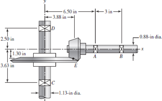
Repeat the analysis of Prob. 3–74 for shaft AB. Assume that bearing A carries the thrust load.
3–74* In the figure, shaft AB transmits power to shaft CD through a set of bevel gears contacting at point E. The contact force at E on the gear of shaft CD is determined to be (FE)CD = ‒92.8i ‒ 362.8j + 808.0k lbf. For shaft CD: (a) draw a free-body diagram and determine the reactions at C and D assuming simple supports (assume also that bearing C carries the thrust load), (b) draw the shear-force and bending-moment diagrams, (c) for the critical stress element, determine the torsional shear stress, the bending stress, and the axial stress, and (d) for the critical stress element, determine the principal stresses and the maximum shear stress.
Want to see the full answer?
Check out a sample textbook solution
Chapter 6 Solutions
Shigley's Mechanical Engineering Design (McGraw-Hill Series in Mechanical Engineering)


- Solve the preceding problem for the following data:P = 160 kN,JV = 200 tN,L = 2 m,b = 95 mm, h = 300 mm, and d = 200 mmarrow_forward, Solve the preceding problem using the numerical data: /) = 90mm, h = 280 mm, d = 210 mm, q = 14 kN/m, and L = L2 m.arrow_forwardThree round, copper alloy bars having the same length L but different shapes are shown, in the figure. The first bar has a diameter d over its entire length, the second has a diameter d over one-fifth of its length, and the third has a diameter d over one-fifteenth of its length. Elsewhere, the second and third bars have a diameter Id. All three bars are subjected to the same axial load P. Use the following numerical data: P = 1400 kN, L = 5m,d= 80 mm, E= 110 GPa. and v = 0.33. (a) Find the change in length of each bar. (b) Find the change in volume of each bar.arrow_forward
- The strength-to-weight ratio of a structural material is defined as its load-carrying capacity divided by its weight. For materials in tension, use a characteristic tensile stress obtained from a stress-strain curve as a measure of strength. For instance, either the yield stress or the ultimate stress could be used, depending upon the particular application. Thus, the strength-to-weight ratio RS/Wfor a material in tension is defined as Rs/w= in which a is the characteristic stress and 7 is the weight density. Note that the ratio has units of length. Using the ultimate stress Uas the strength parameter, calculate the strength-to-weight ratio (in units of meters) for each of the following materials: aluminum alloy 606I-T6, Douglas fir (in bending}, nylon. structural steel ASTM-A57.2, and a titanium alloy. Obtain the material properties from Tables [-1 and 1-3 of Appendix I. When a range of values is given in a table, use the average value.arrow_forwardRepeat Problem 2.4-8, but assume that the bar is made of aluminum alloy and that BC is prismatic. Assume that P = 20 kim. L = 3 ft.t = 314 in., b1 2m.b 2.Sin.andElO.400ksi.arrow_forwardSolve the preceding problem if the collar has mass M = 80 kg, the height h = 0.5 m, the length L = 3.0 m, the cross-sectional area A = 350mm2. and the modulus of elasticity E = 170 GPa.arrow_forward
- Repeat Problem 11.3-9. Use two C 150 × 12.2 steel shapes and assume that E = 205 GPa and L = 6 m.arrow_forwardCompare the angle of twist 1 for a thin-walled circular tube (see figure) calculated from the approximate theory for thin-walled bars with the angle of twist 2 calculated from the exact theory of torsion for circular bars, Express the ratio 12terms of the non-dimensional ratio ß = r/t. Calculate the ratio of angles of twist for ß = 5, 10, and 20. What conclusion about the accuracy of the approximate theory do you draw from these results?arrow_forwardSolve the preceding problem for a W 200 × 41,7 shape with h = 166 mm, h = 205 mm. rw = 7.24 mm, tE= ILS mm,andV = 38 kN.arrow_forward
- Solve the preceding problem if the cross- sectional dimensions are b = 1.5 in. and h = 5.0 in., the gage angle is ß = 750, the measured strains are = 209 × 10-6 and B = -110 × 10, and the material is a magnesium alloy with modulus E = 6.0 X 10⁶ psi and Poisson’s ratio v = 0.35.arrow_forwardThe stresses acting on a stress element on the arm of a power excavator (see figure) are ax= 52 MPa and txy= 33 MPa (sec figure). What is the allowable range of values for the stress if the maximum shear stress is limited to = 37 MPa?arrow_forwardA shock mount constructed as shown iu the figure is used to support a delicate instrument. The mount consists of an outer steel tube with inside diameter b. a central steel bar of diameter d that supports the load P, and a hollow rubber cylinder (height /r) bonded to the tube and bar (a) Obtain a formula Tor the shear stress t in the rubber at a radial distance r from the center of the shock mount. (b) Obtain a formula Tor the downward displacement S of the central bar due to the load P. assuming that G is the shear modulus of elasticity of the rubber and that the steel tube and bar are rigid.arrow_forward
 Mechanics of Materials (MindTap Course List)Mechanical EngineeringISBN:9781337093347Author:Barry J. Goodno, James M. GerePublisher:Cengage Learning