
Concept explainers
The value of the output resistance
Answer to Problem 8.47P
Thevalue of output resistance is
Explanation of Solution
Calculation:
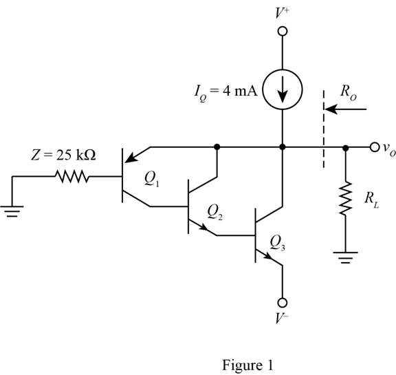
The given diagram is shown in Figure 1.
The expression for the value of base current of transistor
The expression for the value of the collector current for transitory
The expression for the value of the base current for transistor
The expression for the value of the base current for the transistor
The expression for the value of
The expression for the value of the collector current through the transistor
The expression for the value of the collector current for the transistor
The expression for the value of the collector current for transistor
The conversion from
The conversion from
The expression for the value of the quiescent current is given by,
Substitute
Substitute
The expression for the value of the collector current
Substitute
Substitute
Substitute
The expression for the value of
The expression for the value of
The expression for the value of
Substitute
Substitute
The expression for the value of
Substitute
The expression for the value of current
Substitute
The expression to determine the value of
Substitute
Substitute
Conclusion:
Therefore, the value of output resistance is
Want to see more full solutions like this?
Chapter 8 Solutions
Microelectronics: Circuit Analysis and Design


- The fixed bias circuit shown in figure uses a silicon transistor with VBE = 0.7V. Find the collector current, IC (if β of transistor is 60)arrow_forward........ (Figure-1) R. RB= 380kN,Rc= 1kN B = 100, VBB = Vcc=12V RB ww Vec CC ......... I, V CE СЕ V ВЕ BB Q-1-b) Describe briefly the input / output characteristics and application of Common Emitter BJT Configurationarrow_forward3. Write down which transistor structure each curve characteristic belongs to in the figure. Ip -VGS -VGS +VGs (c) VGS (b) (a)arrow_forward
- 2. For the emitter-stabilized bias circuit, determine: a. IBo. b. Ica. c. VCEQ. d. Vc. e. VB. f. VE. 20 V 470 2 ICQ 270 k2 oVc VB B= 125 VCEQ OVE IBQ 2.2 k2arrow_forwardFor the Enhancement-type MOSFET in following figure, 1.Determine IDQ and VGSQarrow_forwardThe DC Current Gain of a Transistor is Select one: a. Ratio of Collector Current to Base Current b. Ratio of Base Current to Collector Current c. Ratio of Emitter Current to Collector Current d. Ratio of Base Current to Emitter Currentarrow_forward
- circuits by using the small signal models of the transistor. Assume the Early voltage of the transistors are infinitely large. Calculate the small-signal input and output impedances of the following Vcc R1 R1 Rout VB RE Rin R2arrow_forwardcircuit diagram with a load ,for the Power MOSFETarrow_forwardDraw the circuit diagram of a resistance–capacitance coupled source followerarrow_forward
- topic (BJT) Determine:a) Transistor terminal voltagesb) Transistor junction voltages show the complete process of solution and write legiblyarrow_forwardIn this voltage divider bias circuit, the input is at the base. Output is at the emitter with a high input resistance and low output resistance. The maximum voltage gain is 1 and the coupling capacitors must have a negligible reactance at the frequency of operation. (use to answer a and b) a. Derive the expression for the voltage gain, current gain, and power gain in terms of power delivered to the load, R. b. Sketch both the DC and AC equivalent circuits. c. Derive the expression for ripple factor of Half Wave Rectification with a capacitor filter.arrow_forward04:- Design a bias circuit for NPN silicon transistor having a nominal B-100 to be used in voltage divider circuit with Q-point of Ic 10 mA and VCE = 10 V. Use standard valued 5% resistors and draw a schematic diagram of your design. (10 points)arrow_forward
 Introductory Circuit Analysis (13th Edition)Electrical EngineeringISBN:9780133923605Author:Robert L. BoylestadPublisher:PEARSON
 Delmar's Standard Textbook Of ElectricityElectrical EngineeringISBN:9781337900348Author:Stephen L. HermanPublisher:Cengage Learning
 Programmable Logic ControllersElectrical EngineeringISBN:9780073373843Author:Frank D. PetruzellaPublisher:McGraw-Hill Education
 Fundamentals of Electric CircuitsElectrical EngineeringISBN:9780078028229Author:Charles K Alexander, Matthew SadikuPublisher:McGraw-Hill Education
 Electric Circuits. (11th Edition)Electrical EngineeringISBN:9780134746968Author:James W. Nilsson, Susan RiedelPublisher:PEARSON
 Engineering ElectromagneticsElectrical EngineeringISBN:9780078028151Author:Hayt, William H. (william Hart), Jr, BUCK, John A.Publisher:Mcgraw-hill Education,