
Concept explainers
Videos
The Geneva
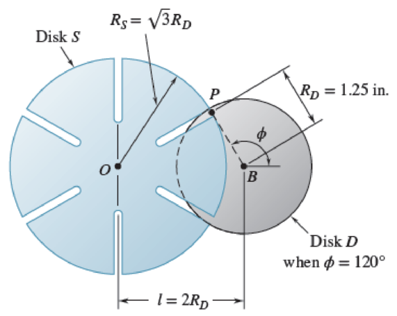
Fig. P16.164
Want to see the full answer?
Check out a sample textbook solution
Chapter 16 Solutions
Vector Mechanics for Engineers: Statics and Dynamics
Additional Engineering Textbook Solutions
Thermodynamics: An Engineering Approach
Machine Elements in Mechanical Design (6th Edition) (What's New in Trades & Technology)
Statics and Mechanics of Materials
Automotive Technology: Principles, Diagnosis, And Service (6th Edition) (halderman Automotive Series)
Thinking Like an Engineer: An Active Learning Approach (4th Edition)
Shigley's Mechanical Engineering Design (McGraw-Hill Series in Mechanical Engineering)


- Problem 8 Another Gear Two disks are connected to one another with a belt as shown. Both disks have mass m but the larger one has radius 4R and the smaller has radius R. The larger disk is powered by a motor that produces a constant torque, To, in the counter- clockwise direction. (a) By using the rotational equivalent of Newton's laws on the larger disk show that the difference in the tension at the top with the tension at the bottom is: Tto - Thot 1 4R (TO - 2m Ra), where a is the linear accleration of the elt. (b) Do the same (find Ttop - Tbot) with the smaller disk. (c) Use your two expressions to find the gular acceleration of the smaller disk. You answer should have m, R, and To in it only. (Careful, the sr aller disk does not have the same angular acceleration as the larger one).arrow_forwardConsider the mechanism shown. Members PQ and QR are joined by a hinge at Q. End P of member PQ is pin-supported and end R of member QR is constrained to move along a horizontal surface. Member PQ rotates clockwise at a constant rate of 12 rad/s. Member QR rotates counterclockwise at a rate of 3.84 rad/s. Which of the following gives the closest value to the magnitude of the angular acceleration of rod QR? 9.16, 6.18, 1.609, 35.2 rad/s^2?? Which of the following gives the closest value to the magnitude of the acceleration of point R? 3.13, 9.89, 10.28, 12.88 m/s^2??arrow_forwardThe swinging frame of a balancing machine is shown in figure 1. The lever ACB has a mass of 6 kg and a radius of gyration of 75 mm about its centre of gravity which is at pivot C. The lever FD is of uniform section and has a mass of 1 kg. It carries a mass of 0,75 kg at E. The mass of the connecting link at BD may be ignored. The stiffness of the compression springs at A and B is 5,6 kg/m. Determine the frequency of vibration of the system. F 50 350 300 E 100 B D Fig. 1 mf SXA Free body diagram SXB Barrow_forward
- A band and block brake having 10 blocks, each of which subtends an angle of 14o at center, is applied todrum of effective diameter of 1 m. The brake drum and winding drum of crane mounted on the sameshaft weighs 20 kN and have combined radius of gyration of 300 mm. The two ends of the band areattached to the pin on opposite side of the fulcrum. If an effort of 300 N is applied at distance of 800mm from the fulcrum, find (i) Braking torque, (ii) the angular retardation of the brake, (iii) the timetaken by the system to come to rest from the rated speed of 400 rpm. Take coefficient of frictionbetween the drum and the block as 0.25.arrow_forwardThe figure below shows a landing gear mechanism for a light aircraft. The weight of the wheel is estimated approximately as 100 lb. Thus it is required to implement a motor capable to lift this weight during the retraction and extraction. The radius of gyration has been determined experimentally as 1.2 feet. In order to achieve a safe operation, a motor is selected adequately with an angular velocity of 3 rad/s, and an angular acceleration of 10 rad/s. It should be noted that such motor will be connected to the shortest link causing a counter clock wise rotation for the input link. Determine the following: a) Determine the closure loop equations. b) Determine the coefficients of the implicit function given as: Acos0, + Bsin0, +C=0 d) Derive an expression for the angular displacement of the coupler, and find its value. e) Derive an expression for the transmission angle and find its value. f) Determine the output angle. g) Using the closure equation find the velocity of point B h) Using…arrow_forwardFigure 5 shows a lever ABC pivoted at B and having a mass of 6 kg and a grinding radius of 75 mm at B. The lever GDF has a uniform section pivoted at G and has a mass of 1.2 kg. It carries a mass of I kg in F. The ECD chain has a mass of 1 kg and always moves on a vertical axis. It carries a mass of 1kg in E. K1 and K2 spring has a constant of 400 N/m and 1 kNm. Find the natural E K, 50 mm B C A K2 200 mm 300 mm 50 mm G F 350 mm 100 mm frequency of the system. Ignore all pendulum effects. [Ans: 14.68 rad/s]arrow_forward
- Given: The gear shown moves on a fixed horizontal rack. The gear has mass m and a radius of gyration of k equal to its radius. The rod BC connected to the gear has length 1, and mass 2m with center of mass located at pt. G. The slider at B has negligible mass, and the attached spring has a spring constant k equal to mg/l. The system is released from rest in a vertical position (the bar BC is vertical). In this position, the spring is unstretched. The system has negligible friction and mass of the spring. k mrod G R mrod = 2m mgear = m l, I= mgear, k Find: Find the velocity of the point C on the gear after it has moved a distance of 1,/2 to the right.arrow_forwardPlease show graphical method representation for all questions a b and c. please.... Thank you A shaft turning at a uniform speed carries two uniform discs A and B of masses 10kg and 8kg respectively. The centres of the mass of the discs are each 2.5mm from the axis of rotation. The radii to the centres of mass are at right angles. The shaft is carried in bearings C and D between A and B such that AC = 0.3m, AD = 0.9m and AB = 1.2m. It is required to make dynamic loading on the bearings equal and a minimum for any given shaft speed by adding a mass at a radius 25mm in a plane E. Determine: The magnitude of the mass in plane E and its angular position relative to the mass in plane A The distance of the plane E from plane A The dynamic loading on each bearing when the mass in plane E has been attached and the shaft rotates at 200 rev/min. For the bearing loads in the…arrow_forwardThe figure shows a trolley of mass 10 kg that can move freely along a smooth fixed horizontal rail driven by a horizontal applied force, F. Pivoted to the trolley at A is a rigid link AB of mass 2 kg, length 1.5 m and inertia 0.38 kgm² about the centre of gravity of the link, which is located at the midpoint. The link is driven by a motor mounted on the trolley which applies an anticlockwise torque T to the link. When the link is at 30° to the horizontal and the mechanism is undergoing the motion shown in the figure determine the magnitude of the reaction force acting on the link at point A in the x and y directions. The positive sense for x and y is given in the figure, and gravity can be assumed to be 10 m/s². O O O F Rail B Rx = 6.94 N Ry = 21.7 N Rx = 14.29 N Ry = 10.15 N Rx = 19.62 N Ry= 22.48 N Rx = 32.05 N Ry = 45.00 N 30⁰ T w = 2 rad/s a = 1 rad/s² v = 0.5 m/s a = 0.5 m/s² garrow_forward
- A four wheeled trolley car has a total mass 3000kg. Each axle with its two wheels and gears has a total moment of inertia of 32kgm2. Each wheel is of 400mm radius. The centre distance between the two wheels on an axle is 1.4m. Each axle is driven by a motor with a speed ratio of 1.3. Each along with it gear has a moment of inertia of 16kgm2 and rotates in the opposite direction to that of the axle. The centre of mass of the car is 1m above the rails. Calculate the limiting speed of the car when it has to travel around a curve of 250m radius without the wheels leaving the road.arrow_forward3) These two steel wheels both have an outer radius of 1.0 m and a mass of 450 kg. Because of the way in which the mass is distributed, wheel A has a radius of gyration of 0.65 m and wheel B has a radius of gyration of 0.32 m (both about the center axis of the wheel). Wheel A: Wheel B: Each wheel is mounted on a separate shaft and a crate is lifted by winding a rope around the wheel. If a motor applies a moment of 200 N·m to the wheel, calculate how far will a 25-kg crate rise in 8.0 seconds for Wheel A, then Wheel B (assuming that all parts are at rest at t = 0).arrow_forwardProblem 4 The uniform L-shaped bar pivots freely at point P of the slider, which moves along the horizontal rod. Determine the steady- state value of the angle 0 if (а) а — 0 (b) a = g/2. For what value of a would the steady-state value of 0 21 be zero?arrow_forward
 Elements Of ElectromagneticsMechanical EngineeringISBN:9780190698614Author:Sadiku, Matthew N. O.Publisher:Oxford University Press
 Mechanics of Materials (10th Edition)Mechanical EngineeringISBN:9780134319650Author:Russell C. HibbelerPublisher:PEARSON
 Thermodynamics: An Engineering ApproachMechanical EngineeringISBN:9781259822674Author:Yunus A. Cengel Dr., Michael A. BolesPublisher:McGraw-Hill Education
 Control Systems EngineeringMechanical EngineeringISBN:9781118170519Author:Norman S. NisePublisher:WILEY
 Mechanics of Materials (MindTap Course List)Mechanical EngineeringISBN:9781337093347Author:Barry J. Goodno, James M. GerePublisher:Cengage Learning
 Engineering Mechanics: StaticsMechanical EngineeringISBN:9781118807330Author:James L. Meriam, L. G. Kraige, J. N. BoltonPublisher:WILEY