
Concept explainers
Videos
For a rigid body in plane motion, show that the system of the inertial terms consists of
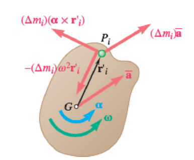
Fig. P16.47
Want to see the full answer?
Check out a sample textbook solution
Chapter 16 Solutions
Vector Mechanics for Engineers: Statics and Dynamics
Additional Engineering Textbook Solutions
Engineering Mechanics: Statics
HEAT+MASS TRANSFER:FUND.+APPL.
DeGarmo's Materials and Processes in Manufacturing
Engineering Mechanics: Statics & Dynamics (14th Edition)
Applied Statics and Strength of Materials (6th Edition)
Vector Mechanics For Engineers


- The 16.2-kg rod is released from rest when θ=0° [position 1]. Knowing that OA=2.025 m, OB=2.7 m. The spring (K=15 N/m}) is unstretched when θ=0°. It reached position (2) when θ=90°. find 1- Kinetic energy when θ=0° 2- polar moment of inertia at O (kg.m2) 3- work done by weight is (Joules) 4- extension of spring when θ=90°. (m) 5- angular velocity when θ=90° (rad/s)arrow_forwardTwo identical giant flywheels are on 2 identical slopes at an angle alpha = 20 deg. One flywheel is rolling on its inside shaft of diameter d1 = 3 ft, and the second flywheel is rolling without slipping on its outside diameter d2 = 5 ft. They are both released from rest. The weight of the flywheel is W = 8 lbs Knowing that flywheel 1 attains a speed of v = 7.0 ft/s in t = [t] s, (if t doesn't show take any t between 5 and 10 sec) find the radius of gyration of the flywheels, following those steps: b. Find omega final c. Find the angular impulse at the point of contact between the shaft and the slope. d. Write the formula to find the final momentum. e. Solve for k, using the principle of angular impulse and momentumarrow_forwardA, B, C and D are four masses carried by a rotating shaft, the masses and eccentricity at B and C are (20 kg, 15 kg) and (150 mm, 140mm) respectively. The masses at A and D have an eccentricity of 170 mm. The angle between the masses at B and C is 90° and that between the masses at B and A is 200°, both being measured in the same direction. The planes containing masses A and B are 300 mm apart and that between B and C are 400 mm. If the shaft is in complete dynamic balance, determine : 1. The magnitude of the masses at A and D; 2. The distance between planes A and D ; and 3. The angular position of the mass at Darrow_forward
- Given: A uniform slender rod is at rest upon a frictionless horizontal surface when a force (F) is applied in the direction shown. Assume that the rod has mass m and length L. A L Horizontal Plane Given that F = 74lb, L = 7.1 ft, mg = 4.6lb, and 0 = 73deg What is the component of acceleration of the mass at point G in the i direction? Answer: Check What is the component of acceleration of the mass at point G in the j direction? Answer: Check What is the component of angular acceleration of the mass in the k direction? (remember your signs) Answer: Checkarrow_forward1. Determine the kinetic energy of the system of Fig.3.16 at an arbitrary instant in terms of x, including the inertia effects of the springs. 2m ima k. m, No slip 81, E k, m, F77777arrow_forwardA shaft carries four masses A, B, C and D of magnitudes 18 kg, 15 kg, 27 kg, and 22.5 kg respectively and revolving at radii 20 mm, 25 mm, 30 mm and 15 mm respectively. The masses are rotating in the same plane. The angular position of masses B, C and D are 60 degrees , 135 degrees and 270 degrees from mass A. Find the magnitude and position of the balancing mass at a radius of 50 mm,arrow_forward
- A ring of mass m =1 kg and radius R = 1m is attached to a vertical shaft by means of a frictionless pin. Coordinates xyz are fixed to the ring as shown and the frictionless pin at A is aligned with the x-axis. The vertical shaft precesses about the Z-axis with constant angular velocity 2 = 1 rad/s. (a) At a particular moment when 0 = 30° and = 4 rad/s, find the value of Ö . This comes from a sum of the moments about the x-axis. Do not neglect gravity. (b) Find the torque or moment necessary that must be applied about the vertical shaft in order to keep it turning at a constant rate of N = 1 rad/s. Ring R XG A 1 Ixx = lyy =mR? G Iz = mR?arrow_forwardA Dashboard M Events * My Courses da This course The moment of the weight W about the origin O is by definition OD x W. D. W Note sin theta = sin0 %3D mass = 45 kg a = 0.8 m 0= 40°arrow_forward1. (bold type indicates a vector) An object of mass m = 10 kg may rotate in a vertical plane about the fixed point P under the action of gravity. The distance d from the point P to the center of mass C is d = 0.5 m. The moment of inertia Ie about the center of mass C is unknown. The object starts at rest in the position shown and is then released. At the instant of release the acceleration of the center of mass is measured to be a, = (-5 m/sec²)j (i.e., downward). Use the given information to determine the moment of inertià I, about the center of mass. Use g = 10 m/sec?. gravity w go P (f ixed)arrow_forward
- A conservative mechanical system consists of a mass m that is constrained to move along a circle of radius R. The centre of the circle is at the origin O of the coordinate system. The mass is connected to a point A along the â-axis at a distance 2R from the centre of circle with a spring of elastic constant k, so that the corresponding elastic potential has the form Vspring = (k/2)ď², where d is the (varying) distance between the mass and point A. Gravity acts, as usual, along the vertical direction. See the figure for a depiction of the system. 0 m (b) Write down the Lagrangian of the system. (a) How many degrees of freedom does the system have? Indicate generalised coordinates to describe the motion of the system. X (c) Write down the corresponding Euler-Lagrange equation(s).arrow_forwardR - m 130° A hollow wheel of mass given by m 50 kg rolls down an incline of 30° without slipping. The inner radius of the wheel is given by R = 50 mm and its thickness is given by d = 5 mm. Gravity acts down. (a) Show that the moment of inertia of the wheel is given by Ī = 138 125 kg mm². (b) Show that the linear acceleration of the wheel's centre of gravity ā is related to the angular acceleration of the wheel a via a (55 mm)a. = (c) Analyse an appropriate free-body diagram to determine the linear acceleration of the wheel's centre of gravity ā.arrow_forwardA light fixture of negligible mass, has three applied forces acting on it as shown. |F,| = 4 kN 1.2 m 1.2 m 1.2 m 2.8 m |F,| = 6 kN y 45° |F| = 5 kN Using the coordinate system shown, determine in kilonewtons the z component of the reaction force at o - Roz Answer:arrow_forward
 Elements Of ElectromagneticsMechanical EngineeringISBN:9780190698614Author:Sadiku, Matthew N. O.Publisher:Oxford University Press
 Mechanics of Materials (10th Edition)Mechanical EngineeringISBN:9780134319650Author:Russell C. HibbelerPublisher:PEARSON
 Thermodynamics: An Engineering ApproachMechanical EngineeringISBN:9781259822674Author:Yunus A. Cengel Dr., Michael A. BolesPublisher:McGraw-Hill Education
 Control Systems EngineeringMechanical EngineeringISBN:9781118170519Author:Norman S. NisePublisher:WILEY
 Mechanics of Materials (MindTap Course List)Mechanical EngineeringISBN:9781337093347Author:Barry J. Goodno, James M. GerePublisher:Cengage Learning
 Engineering Mechanics: StaticsMechanical EngineeringISBN:9781118807330Author:James L. Meriam, L. G. Kraige, J. N. BoltonPublisher:WILEY