
Concept explainers
Videos
Derive the equation
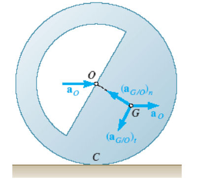
Fig.16.17 Accelerations of the geometric center O and center of mass G for a rolling unbalanced disk.
Want to see the full answer?
Check out a sample textbook solution
Chapter 16 Solutions
Vector Mechanics for Engineers: Statics and Dynamics
Additional Engineering Textbook Solutions
Vector Mechanics for Engineers: Statics
Fox and McDonald's Introduction to Fluid Mechanics
Vector Mechanics for Engineers: Dynamics
Thinking Like an Engineer: An Active Learning Approach (4th Edition)
Vector Mechanics for Engineers: Statics, 11th Edition
Heat and Mass Transfer: Fundamentals and Applications


- A body of mass m and radius of gyration k is to be replaced by two masses m1 and m2 located at distances h1 and h2 from the CG of the original body. An equivalent dynamic system will result, if (A) h1+h2=k (B) h? + h3= k² (C) hıh2=k² h,h2=k² (D)arrow_forwardIn the helicopter shown; a vertical tail propeller is used to pre- vent rotation of the cab as the speed of the main blades is changed. Assuming that the tail propeller is not operating determine the final angular velocity of the cab after the speed of the main blades has been changed from I80 to 240 rpm. (The speed of the main blades is measured relative to the cab, and the cab has a centroidal moment of inertia of 650 lb.ft.s2. Each of the four main blades is assumed to be a slender rod 14 ft weighing 55 lb.)arrow_forward0.08 m,x 0.225 0.75 0.08 m. O: 1.08 b' 0.108 (c) Couple polygon. (d) Force polygon. Fig. 21.11 Page 18 of 19 Balarcing of Rotating Masses H.W. 2: A shaft carries five masses A, B, C, D and E which revolve at the same radius in planes which are equidistant from one another. The magnitude of the masses in planes A. Cand Dare 50 kg. 40 kg and 80 kg respectively. The angle between A and C is 90° and that between C and D is 135°, Determine the magnitude of the masses in planes B and E and their positions to put the shaft in complete rotating balance. 19 Page 19 uf 19 IIarrow_forward
- A rope drum of diameter 850 mm and mass 1000 kg is used in a machine lifting procedure. The drum reaches a top rotational speed of 475 rev/min from rest in a time of 25 s. Determine: (i) the maximum linear speed of the rope;(ii) the angular acceleration of the rope drum;(iii) the moment of inertia of the rope drum, given that its radius of gyration is 250 mm;(iv) the accelerating torque applied to the rope drum.arrow_forward1. A thin pole of length L = 3 m and mass 6 kg is being raised by a rope of tension 80 Newtons as shown. The left end of the pole can rotate about a pivot attached to the wall. Determine the magnitude and direction of the angular acceleration of the pole. The general steps in applying the rotational 2nd law are given below. a. Draw an extended free body diagram showing the forces on the rod and where they act. • The weight acts at the center of mass. • There must be a force at the pivot that holds that end in place. b. Determine the torque generated by each force on your FBD. Sum the torques to get the left-hand side (LHS) of the rotational 2nd law. C. Determine the moment of inertia of the pole. FBD 30° T d. Apply the rotational 2nd law to determine the magnitude and direction of angular acceleration of the pole.arrow_forward4. (20 pts) A concrete block is lifted by a hoisting mechanism in which the cables are securely wrapped around their respective drums. The drums are fastened together and rotate as a single unit at their center of mass O. Combined mass of drum is 150 kg, and radius of gyration at O is 450 mm. A constant tension of 1.8 kN is maintained in the cable by the power unit at A. Determine the vertical acceleration of the block and the resultant force on the bearing at O. 600 mm 300 mm P = 1.8 kN m = 150 kg ko = 450 mm %3D 45° 300 kgarrow_forward
- 1. The turbine rotor of a ship has a mass of 8 tones and a radius of gyration 0.6 m. It rotates at 1800 r.p.m. clockwise, when looking from the stern. Determine the gyroscopic couple, if the ship travels at 100 km/hr and steer to the left in a curve of 75 m radius.arrow_forwardConsider the system formed by the tapered-type flywheel and the 100-kg block shown in the figure below. The block is suspended from an inextensible cord that is wrapped around a pulley of 300-mm radius rigidly attached to the flywheel. The pulley and the flywheel have a combined mass moment of inertia about its center of IT= 0.45 kg. m2. At the instant shown, the velocity of the block is 2 m/s directed downward. If the bearing at O is poorly lubricated and that the bearing friction is equivalent to a couple moment M of magnitude 80 N.m, determine the velocity of the block after it has moved 1 mdownward. Include FBDarrow_forwardA 5.32-kg disk A of radius 0.445 m initially rotating counter-clockwise at 436 rev/min is engaged with a 6.72-kg disk B of radius 0.275 m initially rotating clockwise at 528 rev/min, where the moment of inertia of a disk is given as I = ½ mi?. Determine their combined angular speed (in rpm) and direction of rotation after the meshing of the two disks. Remember to show clearly the equations that you use!!'arrow_forward
- (97) Derive the equations of motion of the system shown in the figure below using Lagrange's equation. The circular cylinder has a mass m and radius r rolls without slipping inside the circular groove of radius R. m, Marrow_forwardA disk with mass m and radius R is released from rest at a height h and rolls without slipping down a ramp. What is the velocity of the center of the disk when it reaches the bottom of the slope? (Hint Use the work-energy principle. At each instant the disk rotates around the contact point C, thus the inertia used for rotatonal kinetic energy should be computed around point C not point G.) m C harrow_forwardA ring of mass m =1 kg and radius R = 1m is attached to a vertical shaft by means of a frictionless pin. Coordinates xyz are fixed to the ring as shown and the frictionless pin at A is aligned with the x-axis. The vertical shaft precesses about the Z-axis with constant angular velocity 2 = 1 rad/s. (a) At a particular moment when 0 = 30° and = 4 rad/s, find the value of Ö . This comes from a sum of the moments about the x-axis. Do not neglect gravity. (b) Find the torque or moment necessary that must be applied about the vertical shaft in order to keep it turning at a constant rate of N = 1 rad/s. Ring R XG A 1 Ixx = lyy =mR? G Iz = mR?arrow_forward
 Elements Of ElectromagneticsMechanical EngineeringISBN:9780190698614Author:Sadiku, Matthew N. O.Publisher:Oxford University Press
 Mechanics of Materials (10th Edition)Mechanical EngineeringISBN:9780134319650Author:Russell C. HibbelerPublisher:PEARSON
 Thermodynamics: An Engineering ApproachMechanical EngineeringISBN:9781259822674Author:Yunus A. Cengel Dr., Michael A. BolesPublisher:McGraw-Hill Education
 Control Systems EngineeringMechanical EngineeringISBN:9781118170519Author:Norman S. NisePublisher:WILEY
 Mechanics of Materials (MindTap Course List)Mechanical EngineeringISBN:9781337093347Author:Barry J. Goodno, James M. GerePublisher:Cengage Learning
 Engineering Mechanics: StaticsMechanical EngineeringISBN:9781118807330Author:James L. Meriam, L. G. Kraige, J. N. BoltonPublisher:WILEY