
Videos
Solve Prob. 16.30, assuming that the direction of motion of the belt is reversed.
16.30 The 180-mm-radius disk is at rest when it is placed in contact with a belt moving at a constant speed. Neglecting the weight of the link AB and knowing that the coefficient of kinetic friction between the disk and the belt is 0.40, determine the angular acceleration of the disk while slipping occurs.
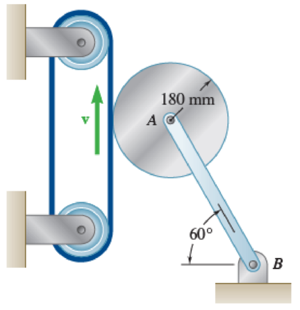
Fig. P16.30
Want to see the full answer?
Check out a sample textbook solution
Chapter 16 Solutions
Vector Mechanics for Engineers: Statics and Dynamics
Additional Engineering Textbook Solutions
Heating Ventilating and Air Conditioning: Analysis and Design
Applied Statics and Strength of Materials (6th Edition)
Fluid Mechanics Fundamentals And Applications
INTERNATIONAL EDITION---Engineering Mechanics: Statics, 14th edition (SI unit)
Fundamentals Of Thermodynamics
Thermodynamics: An Engineering Approach


- A flywheel of centrokdal radius of gyratton K is rigidly attached to a shaft that can roll along parallel rails. Denoting by p, the coeffi- cient of static friction between the shaft and the rails, derive an expression for the largest angle of inclination B for which no slipping will occur. Fig. P16.95 and P16.96arrow_forwardPROBLEM 16.29 The 100-mm-radius brake drum is attached to a flywheel which is not shown. The drum and flywheel together have a mass of 300 kg and a radius of gyration of 600 mm. The coefficient of kinetic friction between the brake band and the drum is 0.30. Knowing that a force P of magnitude 50 N is applied at A when the angular velocity is 180 rpm counterclockwise, determine the time required to stop the flywheel when a = 200 mm and b= 160 mm. B op Drafting& Design Architecturalarrow_forwardThe 200-mm radius brake drum is attached to a larger flywheel that is not shown. The total mass moment of inertia of the drum and the flywheel is 20 kg.m² and the coefficient of kinetic friction between the drum and the brake shoe at B is 0.35. Knowing that the angular velocity of the flywheel is 360 rpm counterclockwise when a force P of magnitude 350 N is applied to the pedal C, determine the number of revolutions executed by the flywheel before it comes to rest. 150 mm 250 mm 200 mm B 375 mmarrow_forward
- The 200-mm-radius brake drum is attached to a larger Bywheel. The total mass moment of inertia of the flywheel and drum is 19 kg. and the coefficient of kinetic friction between the drum and the brake shoe is 035, Knowing that the initial angular velocity of the flywheel is 180 rpm clockwise, determine the vertical force P that must be applied to the pedal C if the system is to stop in 100 revolutions. 150 mm 250 mm B ne: P= 172.88 N C 375 mm 200 mmarrow_forward0.54 m -1.08 m- Fig. P16.61 Fig. P16.60 16.62 Two uniform cylinders, each of mass 7 kg and radius r= 125 mm. are connected by a belt as shown. If the system is released from rest. determine (a) the angular acceleration of each cylinder, (b) the tension in the portion of belt connecting the two cylinders, (c) the velocity of the center of the cylinder A after it has moved through I m. Fig. P16.62arrow_forwardQuestion 4: The brake drum of radius 10 cm is attached is a larger flywheel that is not shown. The total mass moment of inertia of the drum and the flywheel is 50 kg.cm? and the coefficient of kinetic friction between the drum and the brake shoe is 0.35. Knowing that the angular velocity of the flywheel is 360 rpm counterclockwise when a force P of magnitude 40 N is applied to the pedal C, determine the number of revolutions executed by the flywheel before it comes to rest. 15 сm |A 25 cm D 10 cm 35 cm-arrow_forward
- The 12-lb uniform disk shown has a radius of r = 3.2 in. and rotates counterclockwise. Its center C is constrained to move in a slot cut in the vertical member AB, and an 11-lb horizontal force P is applied at B to maintain contact at D between the disk and the vertical wall. The disk moves downward under the influence of gravity and the friction at D. Knowing that the coefficient of kinetic friction between the disk and the wall is 0.12 and neglecting friction in the vertical slot, determine (a) the angular acceleration of the disk, (b) the acceleration of the center C of the disk.arrow_forwardThe 8-in. radius brake drum is attached to a larger flywheel that is not shown. The total mass moment of inertia of the drum and the flywheel is 15 lb.ft.s2 and the coefficient of kinetic friction between the drum and the brake shoe is 0.40. Knowing that the angular velocity of the flywheel is 450 rpm clockwise when a force P of magnitude 65 lbf. is applied to the pedal C, determine the number of the revolutions executed by the flywheel before it comes to rest. (The final answer should be in two decimal places with correct units)arrow_forwardThe 10-in.-radius brake drum is attached to a larger flywheel which is not shown. The total mass moment of inertia of the flywheel and drum is and the coefficient of kinetic friction between the drum and the brake shoe is 0.40. Knowing that the initial angular velocity is 240 rpm clockwise, determine the force that must be exerted by the hydraulic cylinder if the system is to stop in 75 revolutions.arrow_forward
- A 9-kg uniform disk is attached to the 5-kg slender rod AB by means of frictionless pins at B and C. The assembly rotates in a vertical plane under the combined effect of gravity and of a couple M that is applied to rod AB. Knowing that at the instant shown the assembly has an angular velocity of 6 rad/s and an angular acceleration of 25 rad/s2 , both counterclockwise, determine (a) the couple M, (b) the force exerted by pin C on member ABarrow_forward3. The 10-in.-radius brake drum is attached to A a larger flywheel which is not shown. The total mass moment of inertia of the flywheel and drum is 16 lb · ft · s² and the coefficient of kinetic 6 in. friction between the drum and the brake shoe is В 0.40. Knowing that the initial angular velocity is 240 rpm clockwise, determine the force which must be exerted by the hydraulic cylinder if the system is to stop in 75 revolutions. 12 in. D Use work-energy equation. 10 in. +6 in.-arrow_forward16.79 A uniform rod of length L. and mass m is supported as shown. If the cable attached at B suddenly breaks, determine (a) the acceleration of end B. (b) the reaction at the pin support. Fig. P16.79 Barrow_forward
 Elements Of ElectromagneticsMechanical EngineeringISBN:9780190698614Author:Sadiku, Matthew N. O.Publisher:Oxford University Press
 Mechanics of Materials (10th Edition)Mechanical EngineeringISBN:9780134319650Author:Russell C. HibbelerPublisher:PEARSON
 Thermodynamics: An Engineering ApproachMechanical EngineeringISBN:9781259822674Author:Yunus A. Cengel Dr., Michael A. BolesPublisher:McGraw-Hill Education
 Control Systems EngineeringMechanical EngineeringISBN:9781118170519Author:Norman S. NisePublisher:WILEY
 Mechanics of Materials (MindTap Course List)Mechanical EngineeringISBN:9781337093347Author:Barry J. Goodno, James M. GerePublisher:Cengage Learning
 Engineering Mechanics: StaticsMechanical EngineeringISBN:9781118807330Author:James L. Meriam, L. G. Kraige, J. N. BoltonPublisher:WILEY