
Videos
An athlete performs a leg extension on a machine using a 20-kg mass at A located 400 mm away from the knee joint at center O. Biomechanical studies show that the patellar tendon inserts at B, which is 100 mm below point O and 20 mm from the center line of the tibia (see figure). The mass of the lower leg and foot is 5 kg, the center of gravity of this segment is 300 mm from the knee, and the radius of gyration about the knee is 350 mm. Knowing that the leg is moving at a constant angular velocity of 30 degrees per second when θ = 60°, determine (a) the force F in the patellar tendon, (b) the magnitude of the joint force at the knee joint center O.
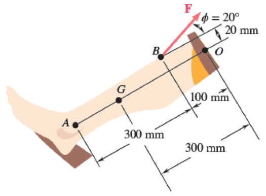
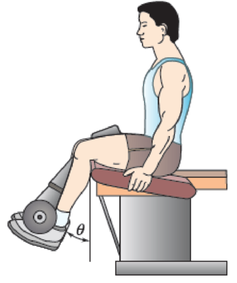
Fig. P16.80
Want to see the full answer?
Check out a sample textbook solution
Chapter 16 Solutions
Vector Mechanics for Engineers: Statics and Dynamics
Additional Engineering Textbook Solutions
INTERNATIONAL EDITION---Engineering Mechanics: Statics, 14th edition (SI unit)
Applied Statics and Strength of Materials (6th Edition)
Fox and McDonald's Introduction to Fluid Mechanics
Engineering Mechanics: Dynamics (14th Edition)
Automotive Technology: Principles, Diagnosis, and Service (5th Edition)
Thermodynamics: An Engineering Approach


- What is the ratio L/R for which the uniform wire figure can be balanced in the position shown?arrow_forwardB. 2. The 4-m boom shown has a mass of 60 kg and is pinned to the back of the truck at point A and secured by a cable at C. Calculate the tension in the cable and the magnitude of the pin force at 4 if the truck accelerates at 5 m/s?. 4 m 60°A 2 marrow_forwardA wheel of mass M has radius R. It is positioned vertically on the floor and you exert a horizontal force F at the center of mass so that it will climb a step against which it rests. (this is like pushing a bike wheel over a curb) If the step has a height h, with harrow_forwardA window cleaner is pulling himself up to a pulley that consists of two disks welded together as shown. The person is currently pulling straight down on the rope in his hands with a force of magnitude 580.4 N. The other rope is also vertical and is attached to the person's center of mass. The person's mass is 74.2 kg, the pulley's total moment of inertia is 395 kgm2, the radius of the small disk is 0.39 m, and the radius of the big disk is 0.73 m.What is the magnitude of the acceleration of the person's center of mass?arrow_forwardAn inside cylinder locomotive has its cylinder centre lines 1 m apart and has a stroke of 1 m. The rotating masses per cylinder are equivalent to 100 kg at the crank pin, and the reciprocating masses per cylinder to 200 kg. The wheel centre lines are 2 m apart. The cranks are at right angles. The whole of the rotating and 2/3 of the reciprocating masses are to be balanced by masses placed at a radius of 0.8 m. Find the magnitude of the balancing mass on the right most wheel. Select one: A. 55.32 kg B. 322.3 kg C. 225.3 kg D. 115.3 kgarrow_forward8. If you stand on one foot while holding your other leg up behind you, your muscles apply a force to hold your leg in this raised position. The leg pivots at the knee joint, and the force that holds the leg up is provided by a tendon attached to the lower leg as shown in the Figure. Assume that the lower leg and the foot have a combined mass of 4.0 kg, and that their combined center of gravity is at the center of the lower leg. a. How much force must the tendon exert to keep the leg in this position? b. As hold your leg in this position, the upper leg exerts a force on the lower leg at the knee joint. you What are the magnitude and direction of this force? The tendon provides the torque to raise the lower leg. 5.0 cm- 50 cmarrow_forward1. An excavator encounters a reaction force of 7600 lb from the ground, normal to line AC, as shown. The shaded structural members (Dipperstick (FH), Mainboom (ADK), bucket, and hydraulic cylinders) have a combined weight of 15000 lb and a horizontal mass center located midway between points C and G. A OLUNU G 3 ft 6 in. 40° E Mainboom 3 ft 4 in. 39 ft F O K Dipperstick H Bucket 7600 lb C Questions: (a) Dismember the shaded structural members (with labeled points A-H) from the tractor and sketch a free-body diagram showing external and exposed internal forces. (b) Compute the force in the hydraulic cylinder strut BD and the pin reactions at A in the given position.arrow_forwardThe figure shows a trolley of mass 10 kg that can move freely along a smooth fixed horizontal rail driven by a horizontal applied force, F. Pivoted to the trolley at A is a rigid link AB of mass 2 kg, length 1.5 m and inertia 0.38 kgm² about the centre of gravity of the link, which is located at the midpoint. The link is driven by a motor mounted on the trolley which applies an anticlockwise torque T to the link. When the link is at 30° to the horizontal and the mechanism is undergoing the motion shown in the figure determine the magnitude of the reaction force acting on the link at point A in the x and y directions. The positive sense for x and y is given in the figure, and gravity can be assumed to be 10 m/s². O O O F Rail B Rx = 6.94 N Ry = 21.7 N Rx = 14.29 N Ry = 10.15 N Rx = 19.62 N Ry= 22.48 N Rx = 32.05 N Ry = 45.00 N 30⁰ T w = 2 rad/s a = 1 rad/s² v = 0.5 m/s a = 0.5 m/s² garrow_forwardAn inside cylinder locomotive has its cylinder centre lines 1 m apart and has a stroke of 1 m. The rotating masses per cylinder are equivalent to 200 kg at the crank pin, and the reciprocating masses per cylinder to 300 kg. The wheel centre lines are 2 m apart. The cranks are at right angles. The whole of the rotating and 2/3 of the reciprocating masses are to be balanced by masses placed at a radius of 0.8 m. Find the value of variation in tractive effort at 300 rpm. Select one: A. ±58476 N B. ±69780 N C. ±79654 N D. ±12475 Narrow_forward1) Diagram below shows four masses M,E,R,S carried by a rotating shaft at radii 100, 125, 200 and 150 mm respectively. The mass of E,R,S are 10 kg, 5 kg, and 4 kg respectively. The planes in which the masses revolve between M and E are 2mm, E and R are 1mm, R and S are 1mm. Determine the required mass of A, mA and the angles a,b,c relative to mass B so that the shaft shall be in complete balance.arrow_forward1. An excavator encounters a reaction force of 7600 lb from the ground, normal to line AC, as shown. The shaded structural members (Dipperstick (FH), Mainboom (ADK), bucket, and hydraulic cylinders) have a combined weight of 15000 lb and a horizontal mass center located midway between points C and G. ΑΠΟ G 3 ft 6 in. 40° E Mainboom 3 ft 4 in. 39 ft Dipperstick H Bucket 7600 lb C ANNAL Questions: (a) Dismember the shaded structural members (with labeled points A-H) from the tractor and sketch a free-body diagram showing external and exposed internal forces. (b) Compute the force in the hydraulic cylinder strut BD and the pin reactions at A in the given position.arrow_forwardQ2: A curved path has banked angle 12° and 30 m radius of rotation was designed for four-wheeled Trolley of total mass 2500 kg to move on track of I m gauge at 35 km/hr. For this vehicle all wheels have an external diameter of 0.5 m and each pair of axle weight is 1800 N and radius of gyration of 0.2 m. The center of gravity is located 1 m above the groun level. Within this mechanism, determine the limited pressure on each rail.arrow_forwardarrow_back_iosSEE MORE QUESTIONSarrow_forward_ios
 International Edition---engineering Mechanics: St...Mechanical EngineeringISBN:9781305501607Author:Andrew Pytel And Jaan KiusalaasPublisher:CENGAGE L