
Shigley's Mechanical Engineering Design (McGraw-Hill Series in Mechanical Engineering)
10th Edition
ISBN: 9780073398204
Author: Richard G Budynas, Keith J Nisbett
Publisher: McGraw-Hill Education
expand_more
expand_more
format_list_bulleted
Videos
Textbook Question
Chapter 9, Problem 14P
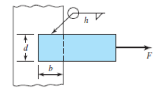
9–13 to 9–16 A steel bar of thickness h is welded to a vertical support as shown in the figure. What is the shear stress in the throat of the welds due to the force F?
| Problem Number | b | d | h | F |
| 9–13 | 50 mm | 50 mm | 5 mm | 100 kN |
| 9–14 | 2 in | 2 in |
|
40 kip |
| 9–15 | 50 mm | 30 mm | 5 mm | 100 kN |
| 9–16 | 4 in | 2 in |
|
40 kip |
Expert Solution & Answer
Want to see the full answer?
Check out a sample textbook solution
Students have asked these similar questions
Q1: The weldment shown in the figure is subjected to a force F. The hot-rolled steel bar has
a thickness h and is of AISI 1040 steel. The vertical support is likewise AISI 1040 HR steel.
The electrode is given in the table below. Estimate the static load F the bar can carry if two
fillet welds are used.
b (mm)
h (mm)
d (mm)
70
Elecrode
E8010
30
6
b→→
F
Q1: The weldment shown in the figure is subjected to a force F. The hot-rolled steel bar has
a thickness h and is of AISI 1040 steel. The vertical support is likewise AISI 1040 HR steel.
The electrode is given in the table below. Estimate the static load F the bar can carry if two
fillet welds are used.
b (mm)
h (mm)
d (mm)
70
Elecrode
E8010
30
6
1-b-
F
Q1: The weldment shown in the figure is subjected to a force F. The hot-rolled steel bar has
a thickness h and is of AISI 1040 steel. The vertical support is likewise AISI 1040 HR steel.
The electrode is given in the table below. Estimate the static load F the bar can carry if two
fillet welds are used.
b (mm)
h (mm)
d (mm)
70
Elecrode
E8010
30
4
Chapter 9 Solutions
Shigley's Mechanical Engineering Design (McGraw-Hill Series in Mechanical Engineering)
Ch. 9 - 91 to 94 The figure shows a horizontal steel bar...Ch. 9 - 91 to 94 The figure shows a horizontal steel bar...Ch. 9 - 91 to 94 The figure shows a horizontal steel bar...Ch. 9 - 91 to 94 The figure shows a horizontal steel bar...Ch. 9 - 95 to 98 For the weldments of Probs. 91 to 94, the...Ch. 9 - 95 to 98 For the weldments of Probs. 91 to 94, the...Ch. 9 - 95 to 98 For the weldments of Probs. 91 to 94, the...Ch. 9 - 95 to 98 For the weldments of Probs. 91 to 94, the...Ch. 9 - 99 to 912 The materials for the members being...Ch. 9 - Prob. 10P
Ch. 9 - Prob. 11PCh. 9 - 99 to 912 The materials for the members being...Ch. 9 - 913 to 916 A steel bar of thickness h is welded to...Ch. 9 - 913 to 916 A steel bar of thickness h is welded to...Ch. 9 - 913 to 916 A steel bar of thickness h is welded to...Ch. 9 - Prob. 16PCh. 9 - Prob. 17PCh. 9 - 917 to 920 A steel bar of thickness h, to be used...Ch. 9 - 917 to 920 A steel bar of thickness h, to be used...Ch. 9 - 917 to 920 A steel bar of thickness h, to be used...Ch. 9 - Prob. 21PCh. 9 - 921 to 924 The figure shows a weldment just like...Ch. 9 - Prob. 23PCh. 9 - Prob. 24PCh. 9 - 9-25 to 9-28 The weldment shown in the figure is...Ch. 9 - 9-25 to 9-28 The weldment shown in the figure is...Ch. 9 - Prob. 27PCh. 9 - 925 to 928 The weldment shown in the figure is...Ch. 9 - The permissible shear stress for the weldment...Ch. 9 - Prob. 30PCh. 9 - 9-30 to 9-31 A steel bar of thickness h is...Ch. 9 - In the design of weldments in torsion it is...Ch. 9 - Prob. 33PCh. 9 - Prob. 34PCh. 9 - The attachment shown carries a static bending load...Ch. 9 - The attachment in Prob. 935 has not had its length...Ch. 9 - Prob. 37PCh. 9 - Prob. 39PCh. 9 - Prob. 40PCh. 9 - Prob. 42PCh. 9 - 9-43 to 9-45 A 2-in dia. steel bar is subjected to...Ch. 9 - 9-43 to 9-45 A 2-in dia. steel bar is subjected to...Ch. 9 - Prob. 45PCh. 9 - Prob. 46PCh. 9 - Find the maximum shear stress in the throat of the...Ch. 9 - The figure shows a welded steel bracket loaded by...Ch. 9 - Prob. 49PCh. 9 - Prob. 50PCh. 9 - Prob. 51PCh. 9 - Brackets, such as the one shown, are used in...Ch. 9 - For the sake of perspective it is always useful to...Ch. 9 - Hardware stores often sell plastic hooks that can...Ch. 9 - For a balanced double-lap joint cured at room...
Knowledge Booster


Learn more about
Need a deep-dive on the concept behind this application? Look no further. Learn more about this topic, mechanical-engineering and related others by exploring similar questions and additional content below.Similar questions
- Q1: The weldment shown in the figure is subjected to a force F. The hot-rolled steel bar has a thickness h and is of AISI 1040 steel. The vertical support is likewise AISI 1040 HR steel. The electrode is given in the table below. Estimate the static load F the bar can carry if two fillet welds are used. d (mm) h (mm) Elecrode b (mm) 30 70 6 E8010 4 ko →arrow_forwardQ1: The weldment shown in the figure is subjected to a force F. The hot-rolled steel bar has a thickness and is of AISI 1040 steel. The vertical support is likewise AISI 1040 HR steel. The electrode is given in the table below. Estimate the static load F the bar can carry if two fillet welds are used. h (mm) b (mm) 30 d (mm) 70 Elecrode E8010arrow_forwardSituation 2: The lap splice shown will develop a full strength as shown in the figure. Using E70 electrodes. The width of the plate is 150 mm and the thickness is 10 mm. Use Fy = 248 MPa T4 46 mm 48 mm 1. Which of the following nearly gives the diameter of the slot weld using the LRFD method. O 45 mm T O 47 mm T Warrow_forward
- Determine the length of the fillet weld lap joint shown in the figure below. The weld has to resist a tension of 115 kips. The effective throat for the weld h = 0.5 inches, and the allowable stress is 21 ksi. length → F = 115 kips harrow_forwardAn AISI 1050 HR solid tube of 20mm diameter is acted by force F1 = IkN, and force F2 of 2kN. The tube is welded to a larger round base by 3mm fillet weldment, the base is connected to the ground base (shown in gray color) by means of four bolts M8x1.25mm (property class of 4.8)). The bolts are evenly distributed at 20mm away from the center of the tube. R=100 F1 120 120. F2 R=100 D =20 120 R=3 D =60 40 Dimensions are in mm Perform the following the following: 1- Find the state of stress for the most critical point on the assembly and build the mohr's circle. Solve question 1arrow_forward1. The welded joint shown below is subjected to a 40 kN of static axial and a 40 kN of static bending loads (F and F1) as shown below. The materials are made of steel with Sut-2070 MPa and Sy=1830MPA. Calculate the factor of safety of the weld. Where, h-6 mm, b-30 mm, c=100 mm d-60 mm, and both forces are equal and each 40 kN (F=F1=40 kN). F F1 d State the reason of your selection in your answer but use only 2 sentences (maximum of 2 lines!) for each answer. 2) Suggest the most suitable bearing type with quantity if a shaft rotates at a speed of 1500 rev/min, subjected to mid-range radial load in a limited radial space. 3) Suggest the most suitable bearing type with quantity if maximum stiffness, stability and resistance to shaft misalignment are desired at a shaft, rotating at 1000 rev/min, under a light radial load. In addition, the shaft is subjected to comparably light thrust loads from either directions. 4) Suggest the most suitable spring type for the following application…arrow_forward
- The carrier plate material St52 (S355) given in the figure below is welded to the body. combined. F1 = 4 kN and F2 = 40 kN static forces act on the plate. Source I. Quality (v2 = 1), no impact (v3 = 1), weld thickness a = 5 mm, safety coefficient s = 2 and weld seam coefficient v1 = 0.8 will be taken. Find out whether a = 5 mm weld seam thickness is sufficient or not, according to the data in the figure and above.arrow_forwardNot yet answered Marked out of 1.00 P Flag question Arectangular cross-section bar is welded to a support by means of fillet welds as shown in Figure below. Determine the size of the welds, if the permissible shear stress in the weld is limited to 75 MPa. 25 kN 500 -150- 100 All dimensions in mmarrow_forwardA bracket shown in the figure is designed to carry a dead weight of W 15000 N. What sizes of fillet welds ae required at top and bottom of the bracket. Assume the forces set through the points A & B. The permissible strength of the-weld is 150 N/mm An 25mm 73mm BTB #-13000N 50mmarrow_forward
- The weldment shown in the figure is subjected to a static force of 100 kN. The hot-rolled steel bar has a thickness h=6 mm and is of AISI 1015 HR steel. The vertical support is AISI 1015 HR steel. The electrode is given in the table below. Use the welding code method. (a) is the weld metal strength satisfactory? (b) Is the attachment strength satisfactory? h h=6 mm b=60 mm d=90mm electrode=E6010 |-b- h Farrow_forward(6) The weldment shown in the figure is subjected to an alternating force F. The hot-rolled steel bar is 10 mm thick and is of AISI 1010 steel. The vertical support is likewise of 1010 steel. The electrode is 6010. Estimate the fatigue load F the bar will carry if three 6-mm fillet welds are used. (22.1 kN) 50 60 Dimensions in millimetersarrow_forwardThe weldment shown in Figure 2 is subjected to an alternating force F. The hot-rolled steel bar is 10 mm thick and is of AISI 1010 steel. The vertical support is likewise of 1010 steel. The electrode is 6010. (a) Estimate the fatigue load F the bar will carry if three 6-mm fillet welds are used. 6. 6 50 F -60 Dimensions in millimetersarrow_forward
arrow_back_ios
SEE MORE QUESTIONS
arrow_forward_ios
Recommended textbooks for you
 Elements Of ElectromagneticsMechanical EngineeringISBN:9780190698614Author:Sadiku, Matthew N. O.Publisher:Oxford University Press
 Mechanics of Materials (10th Edition)Mechanical EngineeringISBN:9780134319650Author:Russell C. HibbelerPublisher:PEARSON
 Thermodynamics: An Engineering ApproachMechanical EngineeringISBN:9781259822674Author:Yunus A. Cengel Dr., Michael A. BolesPublisher:McGraw-Hill Education
 Control Systems EngineeringMechanical EngineeringISBN:9781118170519Author:Norman S. NisePublisher:WILEY
 Mechanics of Materials (MindTap Course List)Mechanical EngineeringISBN:9781337093347Author:Barry J. Goodno, James M. GerePublisher:Cengage Learning
 Engineering Mechanics: StaticsMechanical EngineeringISBN:9781118807330Author:James L. Meriam, L. G. Kraige, J. N. BoltonPublisher:WILEY
Elements Of Electromagnetics
Mechanical Engineering
ISBN:9780190698614
Author:Sadiku, Matthew N. O.
Publisher:Oxford University Press
Mechanics of Materials (10th Edition)
Mechanical Engineering
ISBN:9780134319650
Author:Russell C. Hibbeler
Publisher:PEARSON
Thermodynamics: An Engineering Approach
Mechanical Engineering
ISBN:9781259822674
Author:Yunus A. Cengel Dr., Michael A. Boles
Publisher:McGraw-Hill Education
Control Systems Engineering
Mechanical Engineering
ISBN:9781118170519
Author:Norman S. Nise
Publisher:WILEY
Mechanics of Materials (MindTap Course List)
Mechanical Engineering
ISBN:9781337093347
Author:Barry J. Goodno, James M. Gere
Publisher:Cengage Learning
Engineering Mechanics: Statics
Mechanical Engineering
ISBN:9781118807330
Author:James L. Meriam, L. G. Kraige, J. N. Bolton
Publisher:WILEY
Differences between Temporary Joining and Permanent Joining.; Author: Academic Gain Tutorials;https://www.youtube.com/watch?v=PTr8QZhgXyg;License: Standard Youtube License