
Shigley's Mechanical Engineering Design (McGraw-Hill Series in Mechanical Engineering)
10th Edition
ISBN: 9780073398204
Author: Richard G Budynas, Keith J Nisbett
Publisher: McGraw-Hill Education
expand_more
expand_more
format_list_bulleted
Videos
Textbook Question
Chapter 9, Problem 29P
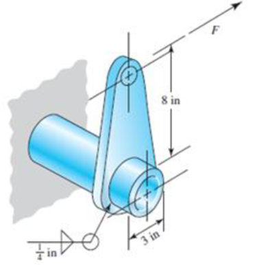
The permissible shear stress for the weldment illustrated is 20 kpsi. Estimate the load, F, that will cause this stress in the weldment throat.
Problem 9–29
Expert Solution & Answer
Want to see the full answer?
Check out a sample textbook solution
Students have asked these similar questions
Two plates, 25 mm thick, are welded together by means of trans verse-fillet welds. The
ultimate tensile strength of a weld metal is 415 MPa. The surface finish factor of the weld
surface is 0.5, and the size factor is 0.85. The reliability is 90%. Determine the length of
the weld if the factor of safety is 2. The transverse force on the welds is 100 kN, which is
completely reversed under fatigue loading. Take: A=10mm
25
Toe
Р.
Q1: The weldment shown in the figure is subjected to a force F. The hot-rolled steel bar has
a thickness h and is of AISI 1040 steel. The vertical support is likewise AISI 1040 HR steel.
The electrode is given in the table below. Estimate the static load F the bar can carry if two
fillet welds are used.
b (mm)
h (mm)
d (mm)
70
Elecrode
E8010
30
6
b→→
F
Q1: The weldment shown in the figure is subjected to a force F. The hot-rolled steel bar has
a thickness h and is of AISI 1040 steel. The vertical support is likewise AISI 1040 HR steel.
The electrode is given in the table below. Estimate the static load F the bar can carry if two
fillet welds are used.
b (mm)
h (mm)
d (mm)
70
Elecrode
E8010
30
6
1-b-
F
Chapter 9 Solutions
Shigley's Mechanical Engineering Design (McGraw-Hill Series in Mechanical Engineering)
Ch. 9 - 91 to 94 The figure shows a horizontal steel bar...Ch. 9 - 91 to 94 The figure shows a horizontal steel bar...Ch. 9 - 91 to 94 The figure shows a horizontal steel bar...Ch. 9 - 91 to 94 The figure shows a horizontal steel bar...Ch. 9 - 95 to 98 For the weldments of Probs. 91 to 94, the...Ch. 9 - 95 to 98 For the weldments of Probs. 91 to 94, the...Ch. 9 - 95 to 98 For the weldments of Probs. 91 to 94, the...Ch. 9 - 95 to 98 For the weldments of Probs. 91 to 94, the...Ch. 9 - 99 to 912 The materials for the members being...Ch. 9 - Prob. 10P
Ch. 9 - Prob. 11PCh. 9 - 99 to 912 The materials for the members being...Ch. 9 - 913 to 916 A steel bar of thickness h is welded to...Ch. 9 - 913 to 916 A steel bar of thickness h is welded to...Ch. 9 - 913 to 916 A steel bar of thickness h is welded to...Ch. 9 - Prob. 16PCh. 9 - Prob. 17PCh. 9 - 917 to 920 A steel bar of thickness h, to be used...Ch. 9 - 917 to 920 A steel bar of thickness h, to be used...Ch. 9 - 917 to 920 A steel bar of thickness h, to be used...Ch. 9 - Prob. 21PCh. 9 - 921 to 924 The figure shows a weldment just like...Ch. 9 - Prob. 23PCh. 9 - Prob. 24PCh. 9 - 9-25 to 9-28 The weldment shown in the figure is...Ch. 9 - 9-25 to 9-28 The weldment shown in the figure is...Ch. 9 - Prob. 27PCh. 9 - 925 to 928 The weldment shown in the figure is...Ch. 9 - The permissible shear stress for the weldment...Ch. 9 - Prob. 30PCh. 9 - 9-30 to 9-31 A steel bar of thickness h is...Ch. 9 - In the design of weldments in torsion it is...Ch. 9 - Prob. 33PCh. 9 - Prob. 34PCh. 9 - The attachment shown carries a static bending load...Ch. 9 - The attachment in Prob. 935 has not had its length...Ch. 9 - Prob. 37PCh. 9 - Prob. 39PCh. 9 - Prob. 40PCh. 9 - Prob. 42PCh. 9 - 9-43 to 9-45 A 2-in dia. steel bar is subjected to...Ch. 9 - 9-43 to 9-45 A 2-in dia. steel bar is subjected to...Ch. 9 - Prob. 45PCh. 9 - Prob. 46PCh. 9 - Find the maximum shear stress in the throat of the...Ch. 9 - The figure shows a welded steel bracket loaded by...Ch. 9 - Prob. 49PCh. 9 - Prob. 50PCh. 9 - Prob. 51PCh. 9 - Brackets, such as the one shown, are used in...Ch. 9 - For the sake of perspective it is always useful to...Ch. 9 - Hardware stores often sell plastic hooks that can...Ch. 9 - For a balanced double-lap joint cured at room...
Knowledge Booster


Learn more about
Need a deep-dive on the concept behind this application? Look no further. Learn more about this topic, mechanical-engineering and related others by exploring similar questions and additional content below.Similar questions
- Q1: The weldment shown in the figure is subjected to a force F. The hot-rolled steel bar has a thickness h and is of AISI 1040 steel. The vertical support is likewise AISI 1040 HR steel. The electrode is given in the table below. Estimate the static load F the bar can carry if two fillet welds are used. b (mm) d (mm) h (mm) Elecrode E8010 30 70 6 ko →→ Farrow_forwardQ1: The weldment shown in the figure is subjected to a force F. The hot-rolled steel bar has a thickness h and is of AISI 1040 steel. The vertical support is likewise AISI 1040 HR steel. The electrode is given in the table below. Estimate the static load F the bar can carry if two fillet welds are used. b (mm) h (mm) d (mm) 70 Elecrode E8010 30 4arrow_forward8. Design the length of weld (L) in the connection below to develop the full tensile capacity of the plate. Use E70 electrodes and 1/4" side fillet welds. The material is ASTM A36 Steel and the allowable axial tensile stress is 22,000 psi. (show all your work) "L" PL 1/2" PL 3/8" x 6" Parrow_forward
- Q1: The weldment shown in the figure is subjected to a force F. The hot-rolled steel bar has a thickness and is of AISI 1040 steel. The vertical support is likewise AISI 1040 HR steel. The electrode is given in the table below. Estimate the static load F the bar can carry if two fillet welds are used. h (mm) b (mm) 30 d (mm) 70 Elecrode E8010arrow_forwardProblem 1: A cylindrical pressure vessel with an inner radius of 1.25 m and a wall thickness of 21 mm is subjected to an internal pressure of 8 MPa. Find the normal stress and shear stress along the 45° weld seam. 45° -1.25 marrow_forwardA bracket is as shown in figure 2. Determine the uniform weld size for the arrangement. The permissible shear stress of weld material is 80 MPa. Consider the loading condition as shown in figure.arrow_forward
- Figure 4 shows a rectangular hollow steel bar welded to a vertical member. The bar has to support a IkN load at its free end. Fillet welds extend all around the outer periphery of the bar. Assuming that the Distortion Energy Theory is applicable, i.e., Say = 0.58 x S, determine the required weld size using a welding rod with S, = 330 MPa and a safety factor of 3 based on yielding. Neglect the weight of the rectangular bar. 1 kN 60 2 25 15 Figure 4 with all dimensions given in millimetresarrow_forwardQ1: The weldment shown in the figure is subjected to a force F. The hot-rolled steel bar has a thickness h and is of AISI 1040 steel. The vertical support is likewise AISI 1040 HR steel. The electrode is given in the table below. Estimate the static load F the bar can carry if two fillet welds are used. d (mm) h (mm) Elecrode b (mm) 30 70 6 E8010 4 ko →arrow_forwardNot yet answered Marked out of 1.00 P Flag question Arectangular cross-section bar is welded to a support by means of fillet welds as shown in Figure below. Determine the size of the welds, if the permissible shear stress in the weld is limited to 75 MPa. 25 kN 500 -150- 100 All dimensions in mmarrow_forward
- appropriate length of the weld joint shown in the figure if the force is equal to (60000lb) and the operating stress value is (60ksi) and the size of the weld is (1/4in).arrow_forwardSituation 2: The lap splice shown will develop a full strength as shown in the figure. Using E70 electrodes. The width of the plate is 150 mm and the thickness is 10 mm. Use Fy = 248 MPa T4 46 mm 48 mm 1. Which of the following nearly gives the diameter of the slot weld using the LRFD method. O 45 mm T O 47 mm T Warrow_forwardDetermine the length of the fillet weld lap joint shown in the figure below. The weld has to resist a tension of 115 kips. The effective throat for the weld h = 0.5 inches, and the allowable stress is 21 ksi. length → F = 115 kips harrow_forward
arrow_back_ios
SEE MORE QUESTIONS
arrow_forward_ios
Recommended textbooks for you
 Elements Of ElectromagneticsMechanical EngineeringISBN:9780190698614Author:Sadiku, Matthew N. O.Publisher:Oxford University Press
 Mechanics of Materials (10th Edition)Mechanical EngineeringISBN:9780134319650Author:Russell C. HibbelerPublisher:PEARSON
 Thermodynamics: An Engineering ApproachMechanical EngineeringISBN:9781259822674Author:Yunus A. Cengel Dr., Michael A. BolesPublisher:McGraw-Hill Education
 Control Systems EngineeringMechanical EngineeringISBN:9781118170519Author:Norman S. NisePublisher:WILEY
 Mechanics of Materials (MindTap Course List)Mechanical EngineeringISBN:9781337093347Author:Barry J. Goodno, James M. GerePublisher:Cengage Learning
 Engineering Mechanics: StaticsMechanical EngineeringISBN:9781118807330Author:James L. Meriam, L. G. Kraige, J. N. BoltonPublisher:WILEY
Elements Of Electromagnetics
Mechanical Engineering
ISBN:9780190698614
Author:Sadiku, Matthew N. O.
Publisher:Oxford University Press
Mechanics of Materials (10th Edition)
Mechanical Engineering
ISBN:9780134319650
Author:Russell C. Hibbeler
Publisher:PEARSON
Thermodynamics: An Engineering Approach
Mechanical Engineering
ISBN:9781259822674
Author:Yunus A. Cengel Dr., Michael A. Boles
Publisher:McGraw-Hill Education
Control Systems Engineering
Mechanical Engineering
ISBN:9781118170519
Author:Norman S. Nise
Publisher:WILEY
Mechanics of Materials (MindTap Course List)
Mechanical Engineering
ISBN:9781337093347
Author:Barry J. Goodno, James M. Gere
Publisher:Cengage Learning
Engineering Mechanics: Statics
Mechanical Engineering
ISBN:9781118807330
Author:James L. Meriam, L. G. Kraige, J. N. Bolton
Publisher:WILEY
Differences between Temporary Joining and Permanent Joining.; Author: Academic Gain Tutorials;https://www.youtube.com/watch?v=PTr8QZhgXyg;License: Standard Youtube License