
Shigley's Mechanical Engineering Design (McGraw-Hill Series in Mechanical Engineering)
10th Edition
ISBN: 9780073398204
Author: Richard G Budynas, Keith J Nisbett
Publisher: McGraw-Hill Education
expand_more
expand_more
format_list_bulleted
Concept explainers
Videos
Textbook Question
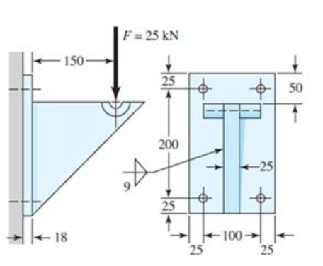
Chapter 9, Problem 47P
Find the maximum shear stress in the throat of the weld metal in the figure.
Problem 9-47
Dimensions in millimeters.
Expert Solution & Answer
Want to see the full answer?
Check out a sample textbook solution
Students have asked these similar questions
The figure shows a solid 2-inch diameter roller that is attached to the wall by means of a permanent clamping. Specify the weld size for the case where the maximum allowable shear stress is 18 kpsi.
Find the maximum shear stress for the stress case given in the figure.
PROBLEM:
Find the values and plot the distribution of stress over the cross section of the upright of the figure. Locate
the point of zero stress.
9,000 N
60 mm thick
100 mm 50
mm
Chapter 9 Solutions
Shigley's Mechanical Engineering Design (McGraw-Hill Series in Mechanical Engineering)
Ch. 9 - 91 to 94 The figure shows a horizontal steel bar...Ch. 9 - 91 to 94 The figure shows a horizontal steel bar...Ch. 9 - 91 to 94 The figure shows a horizontal steel bar...Ch. 9 - 91 to 94 The figure shows a horizontal steel bar...Ch. 9 - 95 to 98 For the weldments of Probs. 91 to 94, the...Ch. 9 - 95 to 98 For the weldments of Probs. 91 to 94, the...Ch. 9 - 95 to 98 For the weldments of Probs. 91 to 94, the...Ch. 9 - 95 to 98 For the weldments of Probs. 91 to 94, the...Ch. 9 - 99 to 912 The materials for the members being...Ch. 9 - Prob. 10P
Ch. 9 - Prob. 11PCh. 9 - 99 to 912 The materials for the members being...Ch. 9 - 913 to 916 A steel bar of thickness h is welded to...Ch. 9 - 913 to 916 A steel bar of thickness h is welded to...Ch. 9 - 913 to 916 A steel bar of thickness h is welded to...Ch. 9 - Prob. 16PCh. 9 - Prob. 17PCh. 9 - 917 to 920 A steel bar of thickness h, to be used...Ch. 9 - 917 to 920 A steel bar of thickness h, to be used...Ch. 9 - 917 to 920 A steel bar of thickness h, to be used...Ch. 9 - Prob. 21PCh. 9 - 921 to 924 The figure shows a weldment just like...Ch. 9 - Prob. 23PCh. 9 - Prob. 24PCh. 9 - 9-25 to 9-28 The weldment shown in the figure is...Ch. 9 - 9-25 to 9-28 The weldment shown in the figure is...Ch. 9 - Prob. 27PCh. 9 - 925 to 928 The weldment shown in the figure is...Ch. 9 - The permissible shear stress for the weldment...Ch. 9 - Prob. 30PCh. 9 - 9-30 to 9-31 A steel bar of thickness h is...Ch. 9 - In the design of weldments in torsion it is...Ch. 9 - Prob. 33PCh. 9 - Prob. 34PCh. 9 - The attachment shown carries a static bending load...Ch. 9 - The attachment in Prob. 935 has not had its length...Ch. 9 - Prob. 37PCh. 9 - Prob. 39PCh. 9 - Prob. 40PCh. 9 - Prob. 42PCh. 9 - 9-43 to 9-45 A 2-in dia. steel bar is subjected to...Ch. 9 - 9-43 to 9-45 A 2-in dia. steel bar is subjected to...Ch. 9 - Prob. 45PCh. 9 - Prob. 46PCh. 9 - Find the maximum shear stress in the throat of the...Ch. 9 - The figure shows a welded steel bracket loaded by...Ch. 9 - Prob. 49PCh. 9 - Prob. 50PCh. 9 - Prob. 51PCh. 9 - Brackets, such as the one shown, are used in...Ch. 9 - For the sake of perspective it is always useful to...Ch. 9 - Hardware stores often sell plastic hooks that can...Ch. 9 - For a balanced double-lap joint cured at room...
Knowledge Booster


Learn more about
Need a deep-dive on the concept behind this application? Look no further. Learn more about this topic, mechanical-engineering and related others by exploring similar questions and additional content below.Similar questions
- Direct a key d the Hub Shear plane Hub Key F2 y, or anical F1 T=Torque Shaft T=F(D/2) F = Force of shaft on key F= Force of hub on key Side view -D Shaft diameter End view Shear Shaft plane Hub F1 Key F2 Shear area = A, = bxL %3D Enlarged view of key Pictorial sketch of key, shaft, and hub Ноуarrow_forwardA member is subjected to a major stress of 110 MPa (tensile), minor stress of 40 MPa (tensile) along with a counter clockwise shear stress of 30 MPa. Calculate the Normal stress, tangential stress, Resultant stress and its inclination on plane make 20 to major stress. Validate your analytical results by drawing Mohr’s circle. i) Normal Stress (unit is MPa) = (ii) Tangential Stress (unit is MPa) = ) Resultant Stress (unit is MPa) Resultant inclination (unit in degree) =arrow_forwardThe steel shafts are connected together using a fillet weld as shown in the figure below. (Figure 1) 12 mm T=60 N-m 12 mm 50 mm- 12 mm 1 12 mm Determine the average shear stress in the weld along section a-s if the torque applied to the shafts is T = 63 N-m. Note: The critical section where the weld fails is along section a-a.arrow_forward
- 03: For the cyclic stress shown in the figure (aside) calculate: 1. The mean stress 2. The range of stress 3. The amplitude 4. The stress ratio 400 400 800 Tension Compression Narrow_forwardare of 10 mm size and the weld length is 30 mm. loading F as shown in figure. Both legs of the fillets considering the minimum throat of the weld, the A fillet welded joint is subjected to transverse loading Fas shown in figure. Both legs of the fillets ere of 10 mm size and the weld length is 30 mm. If the allowable shear stress of the weld is 94 MPa, considering the minimum throat of the weld, the maximum allowable transverse load in kN is Farrow_forwardFind the maximum principal stress for the stress case given in the figure.arrow_forward
- 3- A bracket, as shown in Fig., carries a load of 10 kN. Find the size of the weld if the allowable shear stress is not to exceed 80 MPa. 20 kN 100> -200- All dimensions in mm. 150arrow_forwardFor the stresses given with the cube below: 1. Compute the center, radius (R), principal normal stresses (0₁ and 03), max shear stress (Tmax) and draw the Mohr's Circle. 2. Compute the normal and shear stresses when the cube is rotated 20° clockwise from the horizontal plane and draw them on the cube. 3. The yield point stress (σyp) is 6 kPa. Determine if the material will fail under stresses shown using Tresca's Hexagon. вкра акра 6 экра 8 кра экра 4краarrow_forwardFind the Normal Stress at points A, B, and C in the Rod below. Dimensions given are diameters.arrow_forward
- Find the resultant shear stress at point A & C for the weldment shown in the figure. Leg size of the weld is 10mm. Also show shear stresses on the weld. -300 100 B G, 150 20 kNarrow_forward10/10 find the tensile stress in upper plate in section 3-3 5. 1 4 80 kN 80 kN 8-bolt DIA. 10 MM 80 kN 80 kN 8-bolt DIA. 10 MM 2) 300 mm 8 mmarrow_forwardA rectangular plate (0 =25°) is formed by welding two triangular plates shown in figure. The plate is subjected to a compressive stress of 2.5 MPa in the x-direction and a tensile stress of 15 MPa in the y-direction. Determine the normal stress acting perpendicular to the line of the weld and the shear stress acting parallel to the weld. y Weld Lütfen birini seçin: a. 0.417 MPa/4.38 MPa b. None O c. 0.6256 MPa/6.70 MPa O d. 11.874 MPa/6.70 MPa e. 9.3175 MPa/6.09 MPa O O Oarrow_forward
arrow_back_ios
SEE MORE QUESTIONS
arrow_forward_ios
Recommended textbooks for you
 Mechanics of Materials (MindTap Course List)Mechanical EngineeringISBN:9781337093347Author:Barry J. Goodno, James M. GerePublisher:Cengage Learning
Mechanics of Materials (MindTap Course List)
Mechanical Engineering
ISBN:9781337093347
Author:Barry J. Goodno, James M. Gere
Publisher:Cengage Learning
Pressure Vessels Introduction; Author: Engineering and Design Solutions;https://www.youtube.com/watch?v=Z1J97IpFc2k;License: Standard youtube license