
Shigley's Mechanical Engineering Design (McGraw-Hill Series in Mechanical Engineering)
10th Edition
ISBN: 9780073398204
Author: Richard G Budynas, Keith J Nisbett
Publisher: McGraw-Hill Education
expand_more
expand_more
format_list_bulleted
Concept explainers
Videos
Textbook Question
Chapter 9, Problem 54P
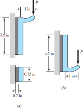
Hardware stores often sell plastic hooks that can be mounted on walls with pressure-sensitive adhesive foam tape. Two designs are shown in (a) and (b) of the figure. Indicate which one you would buy and why.
Problem 9–54
Expert Solution & Answer
Want to see the full answer?
Check out a sample textbook solution
Students have asked these similar questions
A cantilever is to be attached to the flat side of a 6-in wide channel used as a column. The cantilever is to
carry a load as shown in the figure. If two fasteners are used, should the array be arranged vertically,
horizontally, or diagonally? How would you decide? Specify an optimal bolt pattern and size the bolts.
6 in-
6 in
6 in
-in steel plate
+
2000 lbf
Use LRFD and design a 13-foot-long tension member and its connection for a service dead load of 8 kips and a service live load of 24 kips. No slip of the connection is permitted. The connection will be to a 3⁄8-inch-thick gusset plate, as shown in Figure . Use a single angle for the tension member. Use Group A bolts and A572 Grade 50 steel for both the tension member and the gusset plate.
Condition #1:
Å structural support for a machine is subjected to a static compression load of 20 kN. The support is
manufactured from a circular rod made from SAE 1040 Hot Rolled steel. Specify suitable diameter for
the cross section of the rod based on the basic size. Steel data are available in Table A-10 from the
textbook.
Chapter 9 Solutions
Shigley's Mechanical Engineering Design (McGraw-Hill Series in Mechanical Engineering)
Ch. 9 - 91 to 94 The figure shows a horizontal steel bar...Ch. 9 - 91 to 94 The figure shows a horizontal steel bar...Ch. 9 - 91 to 94 The figure shows a horizontal steel bar...Ch. 9 - 91 to 94 The figure shows a horizontal steel bar...Ch. 9 - 95 to 98 For the weldments of Probs. 91 to 94, the...Ch. 9 - 95 to 98 For the weldments of Probs. 91 to 94, the...Ch. 9 - 95 to 98 For the weldments of Probs. 91 to 94, the...Ch. 9 - 95 to 98 For the weldments of Probs. 91 to 94, the...Ch. 9 - 99 to 912 The materials for the members being...Ch. 9 - Prob. 10P
Ch. 9 - Prob. 11PCh. 9 - 99 to 912 The materials for the members being...Ch. 9 - 913 to 916 A steel bar of thickness h is welded to...Ch. 9 - 913 to 916 A steel bar of thickness h is welded to...Ch. 9 - 913 to 916 A steel bar of thickness h is welded to...Ch. 9 - Prob. 16PCh. 9 - Prob. 17PCh. 9 - 917 to 920 A steel bar of thickness h, to be used...Ch. 9 - 917 to 920 A steel bar of thickness h, to be used...Ch. 9 - 917 to 920 A steel bar of thickness h, to be used...Ch. 9 - Prob. 21PCh. 9 - 921 to 924 The figure shows a weldment just like...Ch. 9 - Prob. 23PCh. 9 - Prob. 24PCh. 9 - 9-25 to 9-28 The weldment shown in the figure is...Ch. 9 - 9-25 to 9-28 The weldment shown in the figure is...Ch. 9 - Prob. 27PCh. 9 - 925 to 928 The weldment shown in the figure is...Ch. 9 - The permissible shear stress for the weldment...Ch. 9 - Prob. 30PCh. 9 - 9-30 to 9-31 A steel bar of thickness h is...Ch. 9 - In the design of weldments in torsion it is...Ch. 9 - Prob. 33PCh. 9 - Prob. 34PCh. 9 - The attachment shown carries a static bending load...Ch. 9 - The attachment in Prob. 935 has not had its length...Ch. 9 - Prob. 37PCh. 9 - Prob. 39PCh. 9 - Prob. 40PCh. 9 - Prob. 42PCh. 9 - 9-43 to 9-45 A 2-in dia. steel bar is subjected to...Ch. 9 - 9-43 to 9-45 A 2-in dia. steel bar is subjected to...Ch. 9 - Prob. 45PCh. 9 - Prob. 46PCh. 9 - Find the maximum shear stress in the throat of the...Ch. 9 - The figure shows a welded steel bracket loaded by...Ch. 9 - Prob. 49PCh. 9 - Prob. 50PCh. 9 - Prob. 51PCh. 9 - Brackets, such as the one shown, are used in...Ch. 9 - For the sake of perspective it is always useful to...Ch. 9 - Hardware stores often sell plastic hooks that can...Ch. 9 - For a balanced double-lap joint cured at room...
Knowledge Booster


Learn more about
Need a deep-dive on the concept behind this application? Look no further. Learn more about this topic, mechanical-engineering and related others by exploring similar questions and additional content below.Similar questions
- Draw also free body diagram the bulkhead in problem 5-41arrow_forwardQ1:Prepare a full-section assembly drawing of the four fastener assemblies shown in the Figure. Dimension both the clearance and the threaded holes. A top view may be shown if required. Scale 1: 1. .250-20 FHMS .375 HEX BOLT AND NUT THREADED INTO BASE 1.00 ↓ .50 T 2.00 Ø.375 STUD THREADED .312 HEX X 1.25 LG INTO BASE FOR 1.00 IN. CAP SCREW AND WITH HEX NUT AND LOCK WASHER ON SPOTFACE SURFACE PLATE WASHER A 2.00- -2.00 -1.00- BASE 1.00- .25 1.50arrow_forwardA Draw sectional front view only of a double riveted zigzag lap joint to join two plates of thickness t-10mm (All dimensions must be calculated on a side and marked on the drawing)arrow_forward
- Sketch a V-grooved butt joint, and label all of the joint's dimensions.arrow_forwardA structural support for a machine is subjected to a static compression load of 20 kN. The support is manufactured from a circular rod made from SAE 1040 Hot Rolled steel. Specify suitable diameter for the cross section of the rod based on the basic size. Steel data are available in Table A-10 from the textbook.arrow_forwardProblem 7: Analyse to determine the maximum service tensile live load force that can be supported by a pair of angles 2Ls 152x102x19, shown in the accompanying figure, if 4709M, Grade 345 steel and the AISC LRFD specifications are used. The live load is to be 3/2 times the dead load. The holes are drilled for 18mm rivets at standard gage distances.arrow_forward
- Problem 3: A Hexagonal bolt connects two members. The joint has a gap 1 = 2 in and the applied load is 2000 lb. Both of the clamped parts are steel. A preload of 90% the bolt's proof strength will be applied first. For this design, an SAE grade 1, 5/16"-18 UNC-2A bolt is chosen made from A307 with rolled threads. Washers are included between the head and the joint, and between the nut and the joint. Determine a suitable length for the bolt? Find its safety factor against yielding and against joint separation. Are these values acceptable?arrow_forwardM16 x 2.0 ISO 5.8 coarse series bolts and nuts clamp a 26-mm-thick steel cover plate to a 6-mm-thick steel flange. Steel washers (Size: 16R) are used under the head of the bolt and also under the nut . Assume E = 207 GPa- (a) Determine a suitable length for the bolt, rounded up to the nearest 5 mm. (b) Determine the bolt stiffness. (c) Determine the stiffness of the members. (d) Determine the stiffness of the joint.arrow_forward1)Two blocks with an inclined surface of 100 mm in length, 50 mm in width and 10 mm in thickness were adhered to each other with an adhesive on the curved surfaces seen in the figure. The adhesive has a shear strength of 50 MPa and a tensile strength of 75 MPa. In order for the bonding surface of this block to withstand the axial load of 5000 N in the figure without breaking, the bonding angle should be _____. 2. The flow curve of a brass rod with a diameter of 8 mm and a length of 40 mm is defined by the equation σ = 400 ε0.28 Mpa. The bar shows a yielding rate of 0.2% plastic deformation. If the length of this bar is extended to 50 mm by applying axial tensile stress, how much will the yield strength increase?arrow_forward
- 3.) The diagram below shows a 5.5m long double angle brace which is connected by 6mm welding connection. The length of weld shown in the picture is 300 mm on the top and 100 mm on the bottom. The 2-L127x 89x6.4 are 300W steel and long leg back-to-back. The braces are to be welded to a 12 mm 350W steel gusset plate. Determine the factored tensile capacity of the angles. Any intermediate connections that are required should also be specified. 740 kN -12 mm Gusset Platearrow_forwardTwo 1/4 in × 8 in A36 steel plates are joined with a lap joint using 3/4 in A325-N bolts. If a concentric unfactored live load of 50 kips (dead load = 0) is required to be resisted by the connection and the bolt shear strength controls the design, the minimum required number of bolts is?arrow_forward5. A triple riveted lap joint with zig-zag riveting is to be designed to connect two plates of 6 mm thickness. Determine the dia. of rivet, pitch of rivets and distance between the rows of rivet. Indicate how the joint will fail. Assume : o, = 120 MPa ; t = 100 MPa and o, = 150 MPa. %3D [Ans. d = 14 mm ; p = 78 mm; pb = 35.2 mm] %3Darrow_forward
arrow_back_ios
SEE MORE QUESTIONS
arrow_forward_ios
Recommended textbooks for you
 Welding: Principles and Applications (MindTap Cou...Mechanical EngineeringISBN:9781305494695Author:Larry JeffusPublisher:Cengage Learning
Welding: Principles and Applications (MindTap Cou...
Mechanical Engineering
ISBN:9781305494695
Author:Larry Jeffus
Publisher:Cengage Learning
Understanding Conduction and the Heat Equation; Author: The Efficient Engineer;https://www.youtube.com/watch?v=6jQsLAqrZGQ;License: Standard youtube license