
Concept explainers
Videos
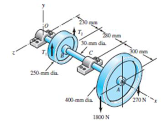
A countershaft carrying two V-belt pulleys is shown in the figure. Pulley A receives power from a motor through a belt with the belt tensions shown. The power is transmitted through the shaft and delivered to the belt on pulley B. Assume the belt tension on the loose side at B is 15 percent of the tension on the tight side.
11-14* to 11-17* For the problem specified in the table, build upon the results of the original problem to obtain a Basic Load Rating for a ball bearing at C with a 95 percent reliability, assuming distribution data from manufacturer 2 in Table 11-6. The shaft rotates at 1200 rev/min, and the desired bearing life is 15 kh. Use an application factor of 1.2.
| Problem Number | Original Problem, Page Number |
| 11-14* | 3-68, 151 |
| 11-15* | 3-69, 151 |
| 11-16* | 3-70, 151 |
| 11-17* | 3-71, 151 |
Problem 3-69*
Want to see the full answer?
Check out a sample textbook solution
Chapter 11 Solutions
Shigley's Mechanical Engineering Design (McGraw-Hill Series in Mechanical Engineering)


- The figure 1 shows a pulley assembly that consists of a shaft supported by two bearings and driven by a motor on the righthand side (not shown in the figure). The shaft diameter is 100mm. The pulley consists of two disks, each disk is 15 mm thick and has an outer diameter of 620mm, that are connected by means of a cylindrical shell. The length of the shell is 500mm, the outer diameter of the shell is 600mm, and the thickness of the shell is 15mm. The pulley drives a belt that places a uniformly distributed load on the shell (of 100000N) as shown in the diagram. The belt lifts a load that applies a torque of 6000Nm to the pulley. The shell and the plates are connected. A 6mm fillet should be applied to all the 90 degree corners between the shaft and the plates and between the shell and the plates. The highest stress in the systemarrow_forwardThe figure 1 shows a pulley assembly that consists of a shaft supported by two bearings and driven by a motor on the righthand side (not shown in the figure). The shaft diameter is 100mm. The pulley consists of two disks, each disk is 15 mm thick and has an outer diameter of 620mm, that are connected by means of a cylindrical shell. The length of the shell is 500mm, the outer diameter of the shell is 600mm, and the thickness of the shell is 15mm. The pulley drives a belt that places a uniformly distributed load on the shell (of 100000N) as shown in the diagram. The belt lifts a load that applies a torque of 6000Nm to the pulley. The shell and the plates are connected. A 6mm fillet should be applied to all the 90 degree corners between the shaft and the plates and between the shell and the plates. Apply the boundary conditions and the forces and torques to the system and determine the following: Calculate the highest Principal stresses in the system ?arrow_forwardA countershaft carrying two V-belt pulleys is shown in the figure. Pulley A receives power from a motor through a belt with the belt tensions shown. The power is transmitted through the shaft and delivered to the belt on pulley B. Assume the belt tension on the loose side at B is 15 percent of the tension on the tight side.arrow_forward
- For nos. 21-23, satisfy the conditions of the given problem below: As an airplane's brakes are applied, the nose wheel exerts two forces on the end of the landing gear as shown in the figure 1. Determine: 21. the force in the strut AB. * 1 point 30° 450 lb. 1350 lb O A. 215.3 lb B. 224.4 lb C. 233. 2 lb D. 234.3 lb 1 ft 2 ftarrow_forwardA gear-reduction unit uses the countershaft depicted in the figure. Find the two bearing reactions.The bearings are to be angular-contact ball bearings, having a desired life of 60 kh when used at 330 rev/min. Use 1.2 for the application factor and a reliability goal for the bearing pair of 0.92arrow_forwardThe degree of freedom of the geared five bar mechanism as shown in figure isarrow_forward
- For nos. 21-23, satisfy the conditions of the given problem below: As an airplane's brakes are applied, the nose wheel exerts two forces on the end of the landing gear as shown in the figure 1. Determine: 21. the force in the strut AB. * 1 ft -20% 2 ft 1350 lb 30% 450 lb. A. 215.3 lb B.224.4 lb C. 233, 2 lb D. 234.3 lb Option 5 22. the horizontal component at the pin C. * A. 628.6 lb B. 627.8 lb C. 634.4 lb D. 652.3 lb 23. the vertical component at the pin C. A. 1468 lb B. 1485 lb C. 1500 lb D. 1526 lbarrow_forwardThe pedal system shown in the figure is exerted by both an up and down mechanism. These forces are Fmax=350*SN/10 N, Fmin=-150*SN/10 N. It is desired that h/b = 5 seen in the figure. This piece is AISI 1040 and has a maximum tensile stress of 670Mpa and a yield stress of 540Mpa. Known weakening factors are known as kb=ky=kd=0.8. The notch factor for all stresses is assumed to be Kç=1.5. It is desired to last up to its minimum indefinite life at the cross-section measurement point (bxh) shown in the figure. According to Goodman theory, what should be the minimum size (b and h value) of this section in order to meet this condition. SN=89arrow_forwardRequired information A countershaft carrying two V-belt pulleys is shown in the figure. Pulley A receives power from a motor through a belt with the belt tensions shown. The power is transmitted through the shaft and delivered to the belt on pulley B. Assume the belt tension on the loose side at B is 15 percent of the tension on the tight side. Given: B(dB) = 205 mm, T(A) = 1880 N, and T(A2) = 282 N. NOTE: This is a multi-part question. Once an answer is submitted, you will be unable to return to this part. B(dB) 230 mm T₂ G 30-mm dia. 100 400-mm dia. T(A₁) 280 mm The bending stress at the point of maximum bending moment is At the point of maximum bending moment, determine the bending stress and the torsional shear stress. The torsional shear stress at the point of maximum bending moment is 300 mm MPa. T(A₂) MPa.arrow_forward
- 19 The figure shows a countershaft carrvino two V-helt pulleys and mounted in bearings at O and C. Fulley A receives power from a motor through a belt wwith the belt tension shown. The power is transmitted through the shaft and delivered to the belt on pullev B. Assume the belt tension on the c) For static analysis using a design factor ng = 2.8, use distortion energy theory to determine the loose side at B is 15 percent of the tension on the right side. The shaft is to be made of AISI 1035 CD steel. a) Determine the tensions in the belt on pulley B, b) Find the reaction forces, minimum safe diameter of the shaft at point A. 250 mo 450 mm 300 mm 2 kN 0.3 kN 200-mm dia. find dia. 250-mm dia.arrow_forwardThe figure illustrates the nonpermanent connection of a steel cylinder head to a grade 30 cast-iron pressure vessel using 73 bolts. A confined gasket seal has an effective sealing diameter D of 0.9 m. The cylinder pressure is cycled between a minimum pressure of zero and a maximum pressure pg of 535 kPa. For the specifications given in the table for the specific problem assigned, select a suitable bolt length from the preferred sizes. Use Table A-17 for calculation purposes. Parameter Value Head thickness, A Cylinder thickness, B Internal diameter of the cylinder, C Gasket sealing diameter, D Bolt circle diameter, E Outer diameter of the cylinder head, 16 mm 25 mm 0.8 m 0.9 m 1.0 m 1.1 m F Bolt grade ISO 10.9 Bolt diameter, d 10 mm NOTE: This is a multi-part question. Once an answer is submitted, you will be unable to return to this part. Find a suitable bolt length. Then, determine the bolt stiffness, material stiffness, and stiffness constant of the joint. The bolt length is 50 mm.…arrow_forwardRequired information A countershaft carrying two V-belt pulleys is shown in the figure. Pulley A receives power from a motor through a belt with the belt tensions shown. The power is transmitted through the shaft and delivered to the belt on pulley B. Assume the belt tension on the loose side at Bis 15 percent of the tension on the tight side. Given: B(dB) = 210 mm, T(AJ = 1720 N, and TA2) = 258 N. 230 mm | T, 280 mm 30-mm dia. 300 mm B(dB) 400-mm dia. T(A2) T(A:) Determine the tensions in the belt on pulley Bassuming the shaft is running at a constant speed. The tension on the loose side of the pulley is N. The tension on the tight side of the pulley is | N.arrow_forward
 Elements Of ElectromagneticsMechanical EngineeringISBN:9780190698614Author:Sadiku, Matthew N. O.Publisher:Oxford University Press
 Mechanics of Materials (10th Edition)Mechanical EngineeringISBN:9780134319650Author:Russell C. HibbelerPublisher:PEARSON
 Thermodynamics: An Engineering ApproachMechanical EngineeringISBN:9781259822674Author:Yunus A. Cengel Dr., Michael A. BolesPublisher:McGraw-Hill Education
 Control Systems EngineeringMechanical EngineeringISBN:9781118170519Author:Norman S. NisePublisher:WILEY
 Mechanics of Materials (MindTap Course List)Mechanical EngineeringISBN:9781337093347Author:Barry J. Goodno, James M. GerePublisher:Cengage Learning
 Engineering Mechanics: StaticsMechanical EngineeringISBN:9781118807330Author:James L. Meriam, L. G. Kraige, J. N. BoltonPublisher:WILEY