
Shigley's Mechanical Engineering Design (McGraw-Hill Series in Mechanical Engineering)
10th Edition
ISBN: 9780073398204
Author: Richard G Budynas, Keith J Nisbett
Publisher: McGraw-Hill Education
expand_more
expand_more
format_list_bulleted
Videos
Textbook Question
Chapter 11, Problem 28P
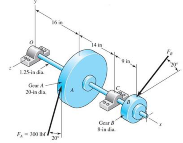
Repeat the requirements of Prob. 11-27 for the bearing at the left end of the shaft.
The shaft shown in the figure is proposed as a preliminary design for the application defined in Prob. 3-72, p. 152. The effective centers of the gears for force transmission are shown. The dimensions for the bearing surfaces (indicated with cross markings) have been estimated. The shaft rotates at 1200 rev/min, and the desired bearing life is 15 kh with a 95 percent reliability in each bearing, assuming distribution data from manufacturer 2 in Table 11-6. Use an application factor of 1.2.
Obtain a Basic Load Rating for a ball bearing at the right end.
Expert Solution & Answer
Want to see the full answer?
Check out a sample textbook solution
Students have asked these similar questions
A 50 mm transmission shaft transmitting 15 kW power at 200 rpm is supported on two deep
grove ball bearings 750 mm apart and two gears are key to it. The pinion and gear have 30
and 100 teeth respectively. The pinion is located at 100 mm to the left of the right bearing,
whereas the gear is located at 150 mm to the right of the left bearing The module and
pressure angle of gear is 5 and 20o involute. Pinion delivers power horizontally to the right
and gear received power in a vertical direction from below as shown in Figure l. The expected
life of 15,00 h assumes the torque is the same for both pinion and gear and the bearings are
under radial load only.
Find the pitch diameters of pinion and gear.
The torque transmits by the shaft
Find force FC and FD
Select suitable deep groove ball bearings at A and B
B
150
500
100
Fe
N-
The figure shows a pair of shaft-mounted spur gears having a diametral pitch of 5 teeth/in with an 18-tooth
20° pinion driving a 45-tooth gear. The power input is 28-hp at 1700 rev/min. Find the magnitude of the
force acting on bearing D.
3
2
3 in 3 in
The magnitude of the force acting on bearing Dis
lbf.
A parallel shaft helical gear consists of a 20
dts drive pinion And a 96 driven gear. Both
gears have a transverse diametrical pitch of
20 dts / in, a helix angle of 25 and a
pressure angle on = 20 . The face width is
4 in., AND the gears are moving at 1600 ft /
min, on the pitch line. The impeller is made
of steel UNSG 10180 CD and without heat
treatment; the driven one is made of grade
30 cast iron. Based on flexural strength
calculations, evaluate the capacity or safe
maximum power at hp. Consider general
industrial service, and nG = 4.
Chapter 11 Solutions
Shigley's Mechanical Engineering Design (McGraw-Hill Series in Mechanical Engineering)
Ch. 11 - Manufacturer Rating Life, Revolutions Weibull...Ch. 11 - Manufacturer Rating Life, Revolutions Weibull...Ch. 11 - Manufacturer Rating Life, Revolutions Weibull...Ch. 11 - Problems 112 and 113 raise the question of the...Ch. 11 - Prob. 5PCh. 11 - Manufacturer Rating Life, Revolutions Weibull...Ch. 11 - Two ball bearings from different manufacturers are...Ch. 11 - 11-8 to 11-13 For the bearing application...Ch. 11 - 11-8 to 11-13 For the bearing application...Ch. 11 - 11-8 to 11-13 For the bearing application...
Ch. 11 - 11-8 to 11-13 For the bearing application...Ch. 11 - 11-8 to 11-13 For the bearing application...Ch. 11 - 11-8 to 11-13 For the bearing application...Ch. 11 - A countershaft carrying two V-belt pulleys is...Ch. 11 - A countershaft carrying two V-belt pulleys is...Ch. 11 - A countershaft carrying two V-belt pulleys is...Ch. 11 - A countershaft carrying two V-belt pulleys is...Ch. 11 - For the shaft application defined in Prob. 3-77,...Ch. 11 - For the shaft application defined in Prob. 3-79,...Ch. 11 - An 02-series single-row deep-groove ball bearing...Ch. 11 - An 02-series single-row deep-groove ball bearing...Ch. 11 - 11-22 to 11-26 An 02-series single-row deep-groove...Ch. 11 - 1122 to 1126 An 02-series single-row deep-groove...Ch. 11 - 1122 to 1126 An 02-series single-row deep-groove...Ch. 11 - 1122 to 1126 An 02-series single-row deep-groove...Ch. 11 - 1122 to 1126 An 02-series single-row deep-groove...Ch. 11 - The shaft shown in the figure is proposed as a...Ch. 11 - Repeat the requirements of Prob. 11-27 for the...Ch. 11 - The shaft shown in the figure is proposed as a...Ch. 11 - Repeat the requirements of Prob. 11-29 for the...Ch. 11 - Shown in the figure is a gear-driven squeeze roll...Ch. 11 - The figure shown is a geared countershaft with an...Ch. 11 - The figure is a schematic drawing of a...Ch. 11 - A gear-reduction unit uses the countershaft...Ch. 11 - The worm shaft shown in part a of the figure...Ch. 11 - In bearings tested at 2000 rev/min with a steady...Ch. 11 - A 16-tooth pinion drives the double-reduction...Ch. 11 - Estimate the remaining life in revolutions of an...Ch. 11 - The same 02-30 angular-contact ball bearing as in...Ch. 11 - A countershaft is supported by two tapered roller...Ch. 11 - For the shaft application defined in Prob. 3-74,...Ch. 11 - For the shaft application defined in Prob. 3-76,...Ch. 11 - Prob. 43PCh. 11 - The gear-reduction unit shown has a gear that is...
Knowledge Booster


Learn more about
Need a deep-dive on the concept behind this application? Look no further. Learn more about this topic, mechanical-engineering and related others by exploring similar questions and additional content below.Similar questions
- The top half of a compound Epicyclic gearset is shown in Figure, with input shaft I rotating at a constant speed of 700 rpm in a clockwise direction and generating 12 kW input power. The Annulus wheel A2 isform a compound wheel with gear O and connected to an auxiliary gear N on shaft X. . The Annulus A1 rotates in a counter-clockwise direction at a speed of 5,300 rpm. Calculate the following using this condition: The speed and direction of output shaft O (NO), shaft X (NX) and gear ratio (n). If Annulus wheel A1 is locked calculate the speed and direction of output shaft O (NO), shaft X (NX) and gear ratio (n). The braking torque (Tb) (magnitude and direction) that must be applied to Annulus wheel A1 to hold it stationary, assuming gear transmission efficiency is 90%. Number of gear teeth:P1 = 30 , A1 = 120P2 = 50 , A2 = 140N = 60 , O = 120arrow_forwardA straight gear with module m = 5 mm and face width bw = 40 mm has center distance cd = 0.1875m. The pinion has 25 teeth, the speed is 1000 rpm, and pressure angle ᶲ = 200. Find the Hertzian contact stress at the pitch point when the gear transmits 10 kW. Neglect friction forces. The gear steel has modulus of elasticity E = 207 GPa and a Poisson’s ratio of 0.30.arrow_forwardThe gear-reduction unit shown has a gear that is press fit onto a cylindrical sleeve that rotates around a stationary shaft. The helical gear transmits an axial thrust load T of 1000 N as shown in the figure. Tangential and radial loads (not shown) are also transmitted through the gear, producing radial ground reaction forces at the bearings of 3200 N for bearing A and 2400 N for bearing B. The desired life for each bearing is 100 kh at a speed of 180 rev/min with a 90 percent reliability. The first iteration of the shaft design indicates approximate diameters of 30 mm at A and at B. Select suitable tapered roller bearings. Barrow_forward
- 1.Please design a pair of spur gears in the milling machine. It is known that power input is 7.5kW, Ni 1450r /min, and the %3D transmission ratio is required to be u = 2.08. F1. If there is slight impact, the supplementary conditions for trial design of this pair of gears: primary selection k = 1.8, number of smaller gear teeth Z1 = 26. The allowable stress and factors for material %3D is: [0]= 600 MPa, [o„]z= 599 MPa, [0,]ı= 220 MPa, [0,]= 213 MPa. E=1.693, Z, =1898/mpa Z„ = 2.5 K =1.25 Ky =1.1 K K =1.2 На K =1.35 Y =2.65, Y = 2.28 Y =1.58 Y =1.76 %3D Fa2 Fal sa1arrow_forwardA steel shaft 800 mm long transmitting 15 kW at 400 r.p.m. is supported at two bearings at the twoends. A gear wheel having 80 teeth and 500 mm pitch circle diameter is mounted at 200 mm from theleft hand side bearing and receives power from a pinion meshing with it. The axis of pinion and gearlie in the horizontal plane. A pulley of 300 mm diameter is mounted at 200 mm from right hand sidebearing and is used for transmitting power by a belt. The belt drive is inclined at 30° to the vertical inthe forward direction. The belt lap angle is 180 degrees. The coefficient of friction between belt andpulley is 0.3. Design and sketch the arrangement of the shaft assuming the values of safe stresses as :τ = 55 MPa; σt= 80 MPa. Take torsion and bending factor 1.5 and 2 respectively.arrow_forwardA short stub shaft, made of SAE 1035, as rolled, receivers 30 hp at 300 rpm via a 12-in. spur gear, the power being delivered to another shaft through a flexible coupling. The gear is keyed (profile keyway) midway between the bearings. The pressure angle of the gear teeth 20o, N = 1.5 based on the octahedral shear stress theory with varying stresses. (a) Neglecting the radial component R of the tooth load W , determine the shaft diameter. (b) Considering both the tangential and the radial components, compute the shaft diameters. (c) Is the difference in the results of the parts (a) and (b) enough to change your choice of the shaft size?arrow_forward
- In a broaching machine shown, shaft A carries a pulley 60.96 cm in diameter which is driven by a leather flat belt from 12-inch pulley on the 30 Hp-squirrel-cage, compensator-motor shaft overhead, the latter turning 1200 rpm. Gears 2 & 4 have 12 teeth each, and 3 & 5 have 60 teeth each. Gear 5 is fast to 6, which has 10 teeth and a module of 8.465 mm/tooth and which engages with rack 7 to which is attached the broach. Assuming that there is no slipping between the pulleys and the belt. Determine: a) the speed with which the broach is drawn through the work, in m/s. b) Specify a double ply, medium weight, cemented joint leather flat belt, considering a mildly jerking loads and a center distance of 60 inches. c) Determine the belt tensions of the belt and the F, maximum stress in the straight part of F₁ ALBA belt if = 3 F₂ Gear 5 Gear 6 Gear 2 DEO CEC A HH₂ Rack 030-0=0 Gear 4 Gear 3arrow_forwardA gear reducer similar to Figure 3–1(a), transmits power from input shaft AB to output shaft CD. The input torque and constant speed are T = 200 lbf-in and ωi = 60 rev/min, respectively. The output load torque and speed are To and ωo, respectively. (c) Shaft AB, with diameter 0.5 in, is supported by ball bearings at A and B, which can be treated as simple supports. For this shaft, the dimension from A to gear G1 is 1.5 in, and gear G1 to B is 2 in. The pitch radii of the gears are r1 = 1.0 in and r2 = 2.5 in. For the spur gears, the pressure angle, ϕ, is 20 degrees. The book name is Shigleys Mechanical Engineering design 11tharrow_forwardProblem 13.049 - Bearing Reactions for Beveled Gears The figure shows a 16T 20° straight bevel pinion driving a 32 T gear and the location of the bearing centerlines. Pinion shaft a receives 2 hp at 200 rev/min. Determine the bearing reactions at A if it is to take both radial and thrust loads. Problem 13-43 Dimensions in inches. The bearing reaction due to radial load FA, radial is | B 4 Ibf and the bearing reaction due to thrust load FA, thrust is Ibf.arrow_forward
- Shaft a in the figure has a power input of 75 kW at a speed of 1000 rev/min in the counterclock-wise direction. The gears have a module of 5 mm and a 20° pressure angle. Gear 3 is an idler.(a) Find the force F3b that gear 3 exerts against shaft b.(b) Find the torque T4c that gear 4 exerts on shaft c.arrow_forward= Q.3: Calculate the power that can be transmitted safely by a pair of spur gears with the data given below and calculate also, the bending stresses induced in the two wheels when the pair transmits this power. Number of teeth in the pinion 20, Number of teeth in the gear = 80, Module = 4 mm, and Width of teeth = 60 mm, Tooth profile involute, Allowable bending strength of the material;( 200 MPa, for = 400 r.p.m and pinion) and (160 MPa, for gear), Speed of the pinion Service factor = 0.8. = 20° Q.4: Design a wire rope for an elevator (Miscellaneous hoists) in a building of (60 m) height, for a total load (20 kN). The speed of the elevator is (240 m/min) and the full speed is reached at (10 sec). Taken the grade wire is (110), the safety factor is 2.5 and Er =84 x 103 N/mm².arrow_forwardThe four helical gears shown in figure have a module in the normal plane of 4 mm and a pressure angle in the normal plane of 0.35 rad. The motor shaft rotates 550 rpm and transmits 20 kW. Other data are on the drawing. (a) What is the speed ratio between the motor (input) and output shafts? (b) Determine all force components that the 20-tooth pinion applies to the 50-tooth gear. Make a sketch showing these forces applied to the gear. (c) The same as part (b), except for the force components that the 50-tooth gear exerts on the 25- tooth pinion 100 50 teeth 200 125 25 teeth ψ = 0.35 rad right hand Motor 20 teeth ψ = 0.50 rad left hand 50 teeth Outputarrow_forward
arrow_back_ios
SEE MORE QUESTIONS
arrow_forward_ios
Recommended textbooks for you
 Elements Of ElectromagneticsMechanical EngineeringISBN:9780190698614Author:Sadiku, Matthew N. O.Publisher:Oxford University Press
 Mechanics of Materials (10th Edition)Mechanical EngineeringISBN:9780134319650Author:Russell C. HibbelerPublisher:PEARSON
 Thermodynamics: An Engineering ApproachMechanical EngineeringISBN:9781259822674Author:Yunus A. Cengel Dr., Michael A. BolesPublisher:McGraw-Hill Education
 Control Systems EngineeringMechanical EngineeringISBN:9781118170519Author:Norman S. NisePublisher:WILEY
 Mechanics of Materials (MindTap Course List)Mechanical EngineeringISBN:9781337093347Author:Barry J. Goodno, James M. GerePublisher:Cengage Learning
 Engineering Mechanics: StaticsMechanical EngineeringISBN:9781118807330Author:James L. Meriam, L. G. Kraige, J. N. BoltonPublisher:WILEY
Elements Of Electromagnetics
Mechanical Engineering
ISBN:9780190698614
Author:Sadiku, Matthew N. O.
Publisher:Oxford University Press
Mechanics of Materials (10th Edition)
Mechanical Engineering
ISBN:9780134319650
Author:Russell C. Hibbeler
Publisher:PEARSON
Thermodynamics: An Engineering Approach
Mechanical Engineering
ISBN:9781259822674
Author:Yunus A. Cengel Dr., Michael A. Boles
Publisher:McGraw-Hill Education
Control Systems Engineering
Mechanical Engineering
ISBN:9781118170519
Author:Norman S. Nise
Publisher:WILEY
Mechanics of Materials (MindTap Course List)
Mechanical Engineering
ISBN:9781337093347
Author:Barry J. Goodno, James M. Gere
Publisher:Cengage Learning
Engineering Mechanics: Statics
Mechanical Engineering
ISBN:9781118807330
Author:James L. Meriam, L. G. Kraige, J. N. Bolton
Publisher:WILEY
BEARINGS BASICS and Bearing Life for Mechanical Design in 10 Minutes!; Author: Less Boring Lectures;https://www.youtube.com/watch?v=aU4CVZo3wgk;License: Standard Youtube License