
Videos
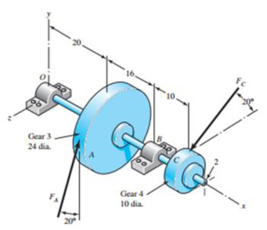
The figure shown is a geared countershaft with an overhanging pinion at C. Select an angular-contact ball bearing from Table 11-2 for mounting at O and an 02-series cylindrical roller bearing from Table 11-3 for mounting at B. The force on gear A is FA = 600 lbf, and the shaft is to run at a speed of 420 rev/min. Solution of the statics problem gives force of bearings against the shaft at O as RO = −387j + 467k lbf, and at B as RB = 3l6j − 1615k lbf. Specify the bearings required, using an application factor of 1.2, a desired life of 40 kh, and a combined reliability goal of 0.95, assuming distribution data from manufacturer 2 in Table 11-6.
Problem 11-32
Dimensions in inches.
Want to see the full answer?
Check out a sample textbook solution
Chapter 11 Solutions
Shigley's Mechanical Engineering Design (McGraw-Hill Series in Mechanical Engineering)


- A steel spur pinion has 16 teeth cut on the 20° full-depth system with a module of 8 mm and a face width of 90 mm. The pinion rotates at 150 rev/min and transmits 4 kW to the mating steel gear. This pinion is to mesh with a steel gear with a gear ratio of 4:1. The Brinell hardness of the teeth is 200, and the tangential load transmitted by the gears is 4 kN. If the contact fatigue strength of the steel can be estimated from the AGMA formula of Sc= 2.22 HB + 200 MPa, estimate the factor of safety of the drive based on a surface fatigue failure. The factor of safety of the drive is 3.086arrow_forwardA 20° 20-tooth cast-iron spur pinion having a module of 4 mm drives a 32-tooth cast-iron gear. Find the contact stress if the pinion speed is 1020 rev/min, the face width is 50 mm, and 10 kW of power is transmitted. Refer to table number 14-8 for elastic coefficient. The contact stress is MPa.arrow_forwardThe reducer input shaft shown in the figure is taperedIt transmits moment with the help of a gear wheel.On the spindle, Fa = 552 N, Fr = 457 N, Ft = 1960 Nfrom gear forces and belt mechanismincoming Fk = 2600 N radial force impact. The shaft rotates with n = 1090 rpm.Accept the shaft diameter in the A bearing as dA = 35 mm.Fixed ball bearing for Lh = 13500 hselectarrow_forward
- For the geared countershaft with an overhanging pinion at C, the force on gear A is FA = 600 Ibf, and the shaft is to run at a speed of 420 rev/min. Consider an application factor of 1.2, a desired life of 40 kh, and combined reliability goal of 0.95 Select and specify the bearing required a) An angular contact ball bearing for mounting at O and b) A straight roller bearing for mounting at B Gear 3 24 dia. Gear 4 10 dia. 20arrow_forwardA 50 mm transmission shaft transmitting 15 kW power at 200 rpm is supported on two deep grove ball bearings 750 mm apart and two gears are key to it. The pinion and gear have 30 and 100 teeth respectively. The pinion is located at 100 mm to the left of the right bearing, whereas the gear is located at 150 mm to the right of the left bearing The module and pressure angle of gear is 5 and 20o involute. Pinion delivers power horizontally to the right and gear received power in a vertical direction from below as shown in Figure l. The expected life of 15,00 h assumes the torque is the same for both pinion and gear and the bearings are under radial load only. Find the pitch diameters of pinion and gear. The torque transmits by the shaft Find force FC and FD Select suitable deep groove ball bearings at A and B B 150 500 100 Fe N-arrow_forwardThe figure shows a 10 diametral pitch 18-tooth 20° straight bevel pinion driving a 38-tooth gear. The transmitted load is 35 lbf. Find the bearing reactions at D on the output shaft if it is to take both radial and thrust loads. Problem 13-44 Dimensions in inches. 3 0 72 이 012441100 2 The bearing reactions at D on the output shaft due to radial load FD, radialis 57.987 lbf and due to thrust load FD, thrust is 4.803 lbf. €arrow_forward
- The reducer input shaft shown in the figure is tapered It transmits moment with the help of a gear wheel. On the spindle, Fa = 552 N, Fr = 457 N, Ft = 1960 N from gear forces and belt mechanism incoming Fk = 2600 N radial force impact . The shaft rotates with n = 1090 rpm. Accept the shaft diameter in the A bearing as dA = 35 mm. Fixed ball suitable for Lh = 13500 h select bearing.arrow_forward3. Figure 4 shows a simplified schematic of the drive system of joint 4 of the PUMA 560. The torsional stiffness of the couplings is 200 Nt-m/radian each, that of the shaft is 400 Nt-m/radian, and each of the reduction gear pairs has been measured to have output stiffness of 2000 Nt-m/radian with its input gears fixed. Both the first and second reductions have n=4. Assuming the structure and bearing are perfectly rigid, a) What is the effective stiffness of gear 1 if the electric motor's shaft is locked? b) What is the effective stiffness of gear 3 if the electric motor's shaft is locked? c) What is the stiffness of the joint (i.e., when the motor's shaft is locked)? In other words, find out the effective stiffness of the output gear 4. - Electric motor -#1 Coupling Connecting rod #2 Coupling -#1 Gear 42 Gear #3 Gear - #4 Gear Figure 4: Simplified version of the driven train of joint 4 of PUMA 560.arrow_forward13-32 The 247 6-pitch 20° pinion 2 shown in the figure rotates clockwise at 1000 rev/min and is driven at a power of 25 hp. Gears 4, 5, and 6 have 24, 36, and 144 teeth, respectively. What torque can arm 3 deliver to its output shaft? Draw free-body diagrams of the arm and of each gear and show all forces that act upon them.arrow_forward
- A cylinder with a nominal 2.5 in ID, a 4.0 in OD, and a 3.0 in length is to be mated with a solid shaft with a nominal 2.5 in diameter. A medium drive fit is desired (as defined in Table 7-9). The cylinder and shaft are made from steel, with Sy = 100 kpsi and E = 30 Mpsi. The coefficient of friction for the steel interface is 0.7. a. Specify the maximum and minimum allowable diameters for both the cylinder hole and the shaft. b. Determine the torque that can be transmitted through this joint, assuming the shaft and cylinder are both manufactured within their tolerances such that the minimum interference is achieved. c. Suppose the shaft and cylinder are both manufactured within their tolerances such that the maximum interference is achieved. Check for yielding of the cylinder at its inner radius by finding the following: i. The pressure at the interface ii. The tangential and radial stresses in the cylinder, at its inner radius. iii. The factor of safety for static yielding of the…arrow_forwardFor the gear mechanism in the figure: P1 = 4 kW, η1 = 1000 rpm, z1 = 18, z2 = 36, z3 = 54, z4 = 108, z1 is the driving gear. Total efficiency values for each stage; Since η12 = η34 = 0.96; Find the output torque and speed of gear z4.arrow_forwardFigure below shows a portion of a pump that is gear-driven at uniform load and speed. The 25 mm diameter solod shaft supported by the bearings is to be made of machined AISI 1045 CD steel. The helical gear is subjected to the axial force F-498 y a radial load F- 750 N and a tangential load of F-1.995 N. Assume the component is g at room temperature of 70F and the material has s0s reliability factor. Hint: Be careful when you calculate the bending moment at the fillet, as all the three forces on the helical gear cause bending moment at the fillet. Calculate resultant bedina moment from all the three forces. Bending moment is completely reversed loading.) 25-mm solid round shaft Fillet Bending K, = 2.0 Torsional k, = 1.5 Axial K,18 F. F, F Pump Helical spur gear -50 mm -250-mm dia FIGURE 1. Identify the critical locations) of stress and show it clearly in a diagram. 2 Identity cleary, all the components of stresses (at the critical point) that will be calcurated (by drawing and clearty…arrow_forward
 Elements Of ElectromagneticsMechanical EngineeringISBN:9780190698614Author:Sadiku, Matthew N. O.Publisher:Oxford University Press
 Mechanics of Materials (10th Edition)Mechanical EngineeringISBN:9780134319650Author:Russell C. HibbelerPublisher:PEARSON
 Thermodynamics: An Engineering ApproachMechanical EngineeringISBN:9781259822674Author:Yunus A. Cengel Dr., Michael A. BolesPublisher:McGraw-Hill Education
 Control Systems EngineeringMechanical EngineeringISBN:9781118170519Author:Norman S. NisePublisher:WILEY
 Mechanics of Materials (MindTap Course List)Mechanical EngineeringISBN:9781337093347Author:Barry J. Goodno, James M. GerePublisher:Cengage Learning
 Engineering Mechanics: StaticsMechanical EngineeringISBN:9781118807330Author:James L. Meriam, L. G. Kraige, J. N. BoltonPublisher:WILEY