
Concept explainers
Videos
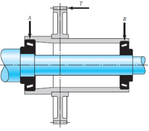
The gear-reduction unit shown has a gear that is press fit onto a cylindrical sleeve that rotates around a stationary shaft. The helical gear transmits an axial thrust load T of 250 lbf as shown in the figure. Tangential and radial loads (not shown) are also transmitted through the gear, producing radial ground reaction forces at the bearings of 875 lbf for bearing A and 625 lbf for bearing B. The desired life for each bearing is 90 kh at a speed of 150 rev/min with a 90 percent reliability. The first iteration of the shaft design indicates approximate diameters of
Problem 11–44
(Courtesy of The Timken Company.)
Want to see the full answer?
Check out a sample textbook solution
Chapter 11 Solutions
Shigley's Mechanical Engineering Design (McGraw-Hill Series in Mechanical Engineering)


- A gear reducer similar to Figure 3–1(a), transmits power from input shaft AB to output shaft CD. The input torque and constant speed are T = 200 lbf-in and ωi = 60 rev/min, respectively. The output load torque and speed are To and ωo, respectively. (c) Shaft AB, with diameter 0.5 in, is supported by ball bearings at A and B, which can be treated as simple supports. For this shaft, the dimension from A to gear G1 is 1.5 in, and gear G1 to B is 2 in. The pitch radii of the gears are r1 = 1.0 in and r2 = 2.5 in. For the spur gears, the pressure angle, ϕ, is 20 degrees. The book name is Shigleys Mechanical Engineering design 11tharrow_forwardFor the gear mechanism in the figure: P1 = 4 kW, η1 = 1000 rpm, z1 = 18, z2 = 36, z3 = 54, z4 = 108, z1 is the driving gear. Total efficiency values for each stage; Since η12 = η34 = 0.96; Find the output torque and speed of gear z4.arrow_forwardIn the figure below, a motor with power 150kw and speed of 2500 rpm is connected to shaft 1(by coupling) in a clockwise direction. Shaft 2 is connected to shaft 1 by gears 1 and 2. If 30% of the power is consumed by the gear3 and 9% by the pulley and 61% by the sprocket, draw torque diagrams for both shafts. If the pressure angle of the gears is 20 degrees to the x-axis, Calculate the reaction forces of the bearings and draw the bending moment diagrams for both shafts according to the information below: Lengths: AB=90mm/BC=DGH=50mm/CD=HI=60mm/DE=IJ=80mm Diameters: dG1=dG2=47mm/ dG3=20mm/ d(pulley)=35mm/d(sprocket)=40mm Gears Gear2 Tew) shaftz Bearing Shaft Gear1 SProcketarrow_forward
- Figure below shows a portion of a pump that is gear-driven at uniform load and speed. The 25 mm diameter solod shaft supported by the bearings is to be made of machined AISI 1045 CD steel. The helical gear is subjected to the axial force F =499 y a radial load F = 741 N and a tangential load of F=2,006 N. Assume the component is operating at room temperature of 70°F and the material has 50% reliability factor. 25-mm solid Bending K, = 2.0 round shaft Fillet Torsional K = 1.5 F. F, Axial K, = 1.8 F Pump Helical spur gear 50 mm -250-mm dia.- FIGURE 1. Identify the critical location(s) of stress and show it clearly in a diagram. 2. Identify cleary, all the components of stresses (at the critical point) that will be calculated (by drawing and clearly showing the XYZ axes) and show it in a matrix form. Show which components of stresses will have a value zero or non-zero. 3. Calculate the principal stresses and principal directions. Show the principal stresses clearly in a stress element…arrow_forwardA 20° 20-tooth cast-iron spur pinion having a module of 4 mm drives a 32-tooth cast-iron gear. Find the contact stress if the pinion speed is 1020 rev/min, the face width is 50 mm, and 10 kW of power is transmitted. Refer to table number 14-8 for elastic coefficient. The contact stress is MPa.arrow_forward427 12T 4 30T In the gear train shown in sketch c the pinion rotates at 520 rpm and transfers 6.9 kW to the train. The circular pitch is 38.25 mm and the pressure angle is 18.5º. Find: 1. the output speed. 2. Draw a free-body diagram of the forces acting on each gear. 3. Find the reaction forces at shaft of the gear 4.arrow_forward
- A 50 mm transmission shaft transmitting 15 kW power at 200 rpm is supported on two deep grove ball bearings 750 mm apart and two gears are key to it. The pinion and gear have 30 and 100 teeth respectively. The pinion is located at 100 mm to the left of the right bearing, whereas the gear is located at 150 mm to the right of the left bearing The module and pressure angle of gear is 5 and 20o involute. Pinion delivers power horizontally to the right and gear received power in a vertical direction from below as shown in Figure l. The expected life of 15,00 h assumes the torque is the same for both pinion and gear and the bearings are under radial load only. Find the pitch diameters of pinion and gear. The torque transmits by the shaft Find force FC and FD Select suitable deep groove ball bearings at A and B B 150 500 100 Fe N-arrow_forwardAs seen in the figure, a construction machine is rotated by a drive mechanism consisting of belt-pulley and spur gear mechanisms. Engine power P = 5.5 kW ; engine shaft speednm = 1500 rpm ; drive pulley diameter Dt = 16 cm ; diameter of the opposite pulley Dk = 55 cm ; number of pinion teeth z1 = 21 ; number of teeth of the counter gearz2 = 60 ; pulley mechanism efficiency ηk = 0.95 ; Since the efficiency of the gear mechanism is ηd = 0.97: a) Find the output shaft speed nç and the torque Mç on this shaft.b) The force on the taut arm of the belt S1 = 450 N;coefficient of friction μ = 0.3 ; If the winding angle α = 160⁰, is the frictionally transmitted moment Ms sufficient to compensate for the Mg moment on the input shaft? Calculate.arrow_forwardThe shaft shown in figure below rotating at 310 rpm carries a spur pinion E. The teeth are of the 20°, full-depth, involute form. The pinion delivers 20 hp to a gear to the left as shown. Compute the torque delivered by the shaft to the pinion E and the tangential and radial forces exerted on the shaft by the pinion. Include the weight of the pinion. A B E -12- Flywheel 1550 lb 22-in dia. V-belt sheave 120 lb 9 A 20° 6-in spur gear 20° FD 45 lb WEE Q E drives Q WrE 45 16.arrow_forward
- A straight gear with module m = 5 mm and face width bw = 40 mm has center distance cd = 0.1875m. The pinion has 25 teeth, the speed is 1000 rpm, and pressure angle ᶲ = 200. Find the Hertzian contact stress at the pitch point when the gear transmits 10 kW. Neglect friction forces. The gear steel has modulus of elasticity E = 207 GPa and a Poisson’s ratio of 0.30.arrow_forwardFigure below shows a portion of a pump that is gear-driven at uniform load and speed. The 25 mm diameter solod shaft supported by the bearings is to be made of machined AISI 1045 CD steel. The helical gear is subjected to the axial force F-498 y a radial load F- 750 N and a tangential load of F-1.995 N. Assume the component is g at room temperature of 70F and the material has s0s reliability factor. Hint: Be careful when you calculate the bending moment at the fillet, as all the three forces on the helical gear cause bending moment at the fillet. Calculate resultant bedina moment from all the three forces. Bending moment is completely reversed loading.) 25-mm solid round shaft Fillet Bending K, = 2.0 Torsional k, = 1.5 Axial K,18 F. F, F Pump Helical spur gear -50 mm -250-mm dia FIGURE 1. Identify the critical locations) of stress and show it clearly in a diagram. 2 Identity cleary, all the components of stresses (at the critical point) that will be calcurated (by drawing and clearty…arrow_forwardEx. #5] Pinion 2 in the figure runs at 1 750 rpm and transmits 2.5 kW to idler gear 3. The teeth are cut on the 20° full-depth system and have a module of m= 2.5 mm. Draw the free body diagram of gear 3 and shows all the forces acting upon it. Determine the forces acting upon gear 3. The direction of rotation of gear 3, as shown, is counterclockwise. GIVEN: Figure shown N₂ = 1750 rpm $=200 P = 2.5 kW m = 2.5 mm 3 0₂ REQUIRED: CS Draw the freechody distram of gear 3 and compute the forces acting on it.arrow_forward
 Elements Of ElectromagneticsMechanical EngineeringISBN:9780190698614Author:Sadiku, Matthew N. O.Publisher:Oxford University Press
 Mechanics of Materials (10th Edition)Mechanical EngineeringISBN:9780134319650Author:Russell C. HibbelerPublisher:PEARSON
 Thermodynamics: An Engineering ApproachMechanical EngineeringISBN:9781259822674Author:Yunus A. Cengel Dr., Michael A. BolesPublisher:McGraw-Hill Education
 Control Systems EngineeringMechanical EngineeringISBN:9781118170519Author:Norman S. NisePublisher:WILEY
 Mechanics of Materials (MindTap Course List)Mechanical EngineeringISBN:9781337093347Author:Barry J. Goodno, James M. GerePublisher:Cengage Learning
 Engineering Mechanics: StaticsMechanical EngineeringISBN:9781118807330Author:James L. Meriam, L. G. Kraige, J. N. BoltonPublisher:WILEY