
Concept explainers
Videos
A 16-tooth pinion drives the double-reduction spur-gear train in the figure. All gears have 25° pressure angles. The pinion rotates ccw at 1200 rev/min and transmits power to the gear train. The shaft has not yet been designed, but the free bodies have been generated. The shaft speeds are 1200 rev/min, 240 rev/min, and 80 rev/min. A bearing study is commencing with a 10-kh life and a gearbox bearing ensemble reliability of 0.99, assuming distribution data from manufacturer 2 in Table 11-6. An application factor of 1.2 is appropriate. For each shaft, specify a matched pair of 02-series cylindrical roller bearings from Table 11-3.
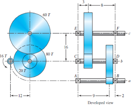
(a)
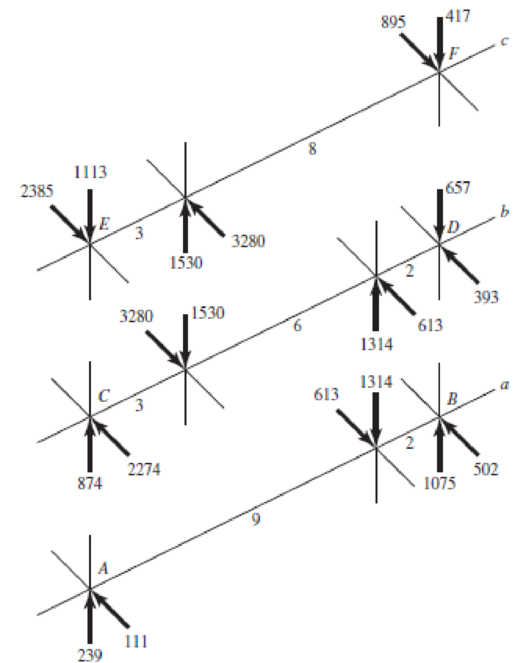
(b) Developed view
Problem 11–37
(a) Drive detail; (b) force analysis on shafts. Forces in pounds; linear dimensions in inches.
Want to see the full answer?
Check out a sample textbook solution
Chapter 11 Solutions
Shigley's Mechanical Engineering Design (McGraw-Hill Series in Mechanical Engineering)


- A parallel shaft helical gear consists of a 20 dts drive pinion And a 96 driven gear. Both gears have a transverse diametrical pitch of 20 dts / in, a helix angle of 25 and a pressure angle on = 20 . The face width is 4 in., AND the gears are moving at 1600 ft / min, on the pitch line. The impeller is made of steel UNSG 10180 CD and without heat treatment; the driven one is made of grade 30 cast iron. Based on flexural strength calculations, evaluate the capacity or safe maximum power at hp. Consider general industrial service, and nG = 4.arrow_forwardThe four helical gears shown in figure have a module in the normal plane of 4 mm and a pressure angle in the normal plane of 0.35 rad. The motor shaft rotates 550 rpm and transmits 20 kW. Other data are on the drawing. (a) What is the speed ratio between the motor (input) and output shafts? (b) Determine all force components that the 20-tooth pinion applies to the 50-tooth gear. Make a sketch showing these forces applied to the gear. (c) The same as part (b), except for the force components that the 50-tooth gear exerts on the 25- tooth pinion 100 50 teeth 200 125 25 teeth ψ = 0.35 rad right hand Motor 20 teeth ψ = 0.50 rad left hand 50 teeth Outputarrow_forwardThe figure shows a pair of shaft-mounted spur gears having a diametral pitch of 5 teeth/in with an 18-tooth 20° pinion driving a 45-tooth gear. The power input is 28-hp at 1700 rev/min. Find the magnitude of the force acting on bearing D. 3 2 3 in 3 in The magnitude of the force acting on bearing Dis lbf.arrow_forward
- 1. The figure shows a pair of shaft-mounted spur gears having a diametrical pitch of 6 teeth/in with a 14 tooth pinion (gear 2) driving a 49 tooth gear at a pressure angle of 20°. The power input is 3/4 hp at 2400 rpm cw. A, B, C, and D are bearings. 3. 3 in 3 in Determine the following: a. The Free Body Diagram for both gears. b. The pitch diameters of gears 2 and 3. c. The transmitted load. d. The torque Tin on the pinion shaft. e. The radial and tangential forces on gear 3 f. The output torque of gear 3 shaft.arrow_forwardPROBLEM A pair of straight bevel gears drives the vertical drilling machine. The approximate speed reduction is 4:1 with the pinion mounted on the horizontal drive shaft. The drill develops a torque of 495 N-m at 550 rpm. Assume the tooth form to be 20° stub, 24 teeth in the pinion and module of 4. The pinion and gear are made of steel (EP=EG= 215GPA) and have a surface hardness of 250 B.H.N. The tooth form factor of the teeth is 14 ½ and take form factor as y' = 0.335. a)Determine the cone distance b)Determine the face width assuming % of the cone distance c)Determine the formative number of teeth on the pinion d)Determine the tangential force e)Determine the determine permissible tooth load (AGMA Standards) f)Determine the maximum limiting load for wear g)Determine the endurance strength for the teetharrow_forward13-31 Shaft a in the figure has a power input of 75 kW at a speed of 1000 rev/min in the counterclock- wise direction. The gears have a module of 5 mm and a 20° pressure angle. Gear 3 is an idler. (a) Find the force F3, that gear 3 exerts against shaft b. (b) Find the torque T4, that gear 4 exerts on shaft c. 517 34T Problem 13-31 3 177arrow_forward
- The top half of a compound Epicyclic gearset is shown in Figure, with input shaft I rotating at a constant speed of 700 rpm in a clockwise direction and generating 12 kW input power. The Annulus wheel A2 isform a compound wheel with gear O and connected to an auxiliary gear N on shaft X. . The Annulus A1 rotates in a counter-clockwise direction at a speed of 5,300 rpm. Calculate the following using this condition: The speed and direction of output shaft O (NO), shaft X (NX) and gear ratio (n). If Annulus wheel A1 is locked calculate the speed and direction of output shaft O (NO), shaft X (NX) and gear ratio (n). The braking torque (Tb) (magnitude and direction) that must be applied to Annulus wheel A1 to hold it stationary, assuming gear transmission efficiency is 90%. Number of gear teeth:P1 = 30 , A1 = 120P2 = 50 , A2 = 140N = 60 , O = 120arrow_forwardIn the double-reduction gear train shown (dimensions are in inches), shaft a is driven by a motor attached by a flexible coupling attached to the overhang. The motor provides a torque of 2500 lbf-in at a speed of 1200 rpm. The gears have 20° pressure angles, with diameters shown in the figure. Use an AISI 1020 cold-drawn steel. Design Shaft CD with a design factor of 1.5 by performing the following tasks. (a) Sketch a general shaft layout, including means to locate the gears and bearings, and to transmit the torque. (b) Perform a force analysis to find the bearing reaction forces, and generate shear and bending moment diagrams. (c) Determine potential critical locations for stress design. (d) Determine critical diameters of the shaft based on fatigue and static stresses at the critical locations. (e) Make any other dimensional decisions necessary to specify all diameters and axial dimensions. Sketch the shaft to scale, showing all proposed dimensions. (f) If any of the deflections…arrow_forwardA 17-tooth 20° pressure angle spur pinion rotates at 1800 rev/min and transmits 4 hp to a 52-tooth disk gear. The diametral pitch is 10 teeth/in, the face width 1.5 in, and the quality standard is No. 6. The gears are straddle-mounted with bearings immediately adjacent. The pinion is a grade 1 steel with a hardness of 240 Brinell tooth surface and through-hardened core. The gear is steel, through-hardened also, grade 1 material, with a Brinell hardness of 200, tooth surface and core. Poisson's ratio is 0.30, Jp = 0.30, JG = 0.40, and Young's modulus is 30(10°) psi. The loading is smooth because of motor and load. Assume a pinion life of 108 cycles and a reliability of 0.90, and use YN = 1.3558N-0.0178, ZN = 1.4488N-0.023. The tooth profile is uncrowned. This is a commercial enclosed gear unit. (a) Find the factor of safety of the gears in bending. (b) Find the factor of safety of the gears in wear. (c) By examining the factors of safety, identify the threat to each gear and to the…arrow_forward
- Problem 13.049 - Bearing Reactions for Beveled Gears The figure shows a 16T 20° straight bevel pinion driving a 32 T gear and the location of the bearing centerlines. Pinion shaft a receives 2 hp at 200 rev/min. Determine the bearing reactions at A if it is to take both radial and thrust loads. Problem 13-43 Dimensions in inches. The bearing reaction due to radial load FA, radial is | B 4 Ibf and the bearing reaction due to thrust load FA, thrust is Ibf.arrow_forwardProblem 1. The spur gears shown in Figure 1 have a diametral pitch of 2 teeth per inch and a 20° - pressure angle. Gear 2 rotates at 1800 rev/min clockwise and transmits 200 hp through the idler pair in Gear 5 on shaft c. (a) Show fully labeled free-body diagrams of gear 2, and Gears 3 and 4; (b) What forces do gear 3 and 4 transmit to the idler shaft? (c) What is the train value? (d) What is the output speed? Gear 5 Gear 4 48Teeth 18Teeth Gear 3 32Teeth Gear 2 18Teeth Figure 1arrow_forwardA pair of steel gears have a design life of a million cycles. They have 20° full-depth teeth with a diametral pitch of 8. Both gear and pinion are made of steel heat-treated to 350 Bhn, and both have a face width of 1.0 in. The teeth are machined with the highest quality hobbing operation. The pinion has 35 teeth and rotates 2000 rpm. The gear diameter over pinion diameter ratio is 2. The gears stay below a temperature of 140 °F. Assume a mounting correction factor of Km = 1.6 and an overload factor of Ko = 1. Use a reliability of 99.9% and a safety factor of 1.5. Use the pinion for the bending fatigue calculations and assume that there is no load sharing. A. What is the fatigue strength for these conditions. B. What is the tangential force acting on the gear teeth? C. Estimate the horsepower that can be transmitted, based only on bending fatigue.arrow_forward
 Elements Of ElectromagneticsMechanical EngineeringISBN:9780190698614Author:Sadiku, Matthew N. O.Publisher:Oxford University Press
 Mechanics of Materials (10th Edition)Mechanical EngineeringISBN:9780134319650Author:Russell C. HibbelerPublisher:PEARSON
 Thermodynamics: An Engineering ApproachMechanical EngineeringISBN:9781259822674Author:Yunus A. Cengel Dr., Michael A. BolesPublisher:McGraw-Hill Education
 Control Systems EngineeringMechanical EngineeringISBN:9781118170519Author:Norman S. NisePublisher:WILEY
 Mechanics of Materials (MindTap Course List)Mechanical EngineeringISBN:9781337093347Author:Barry J. Goodno, James M. GerePublisher:Cengage Learning
 Engineering Mechanics: StaticsMechanical EngineeringISBN:9781118807330Author:James L. Meriam, L. G. Kraige, J. N. BoltonPublisher:WILEY