
Videos
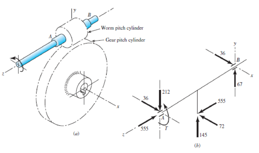
The worm shaft shown in part a of the figure transmits 1.2 hp at 500 rev/min. A static force analysis gave the results shown in part b of the figure. Bearing A is to be an angular-contact ball bearing selected from Table 11-2, mounted to take the 555-lbf thrust load. The bearing at B is to take only the radial load, so an 02-series cylindrical roller bearing from Table 11-3 will be employed. Use an application factor of 1.2, a desired life of 30 kh, and a combined reliability goal of 0.99, assuming distribution data from manufacturer 2 in Table 11-6. Specify each bearing.
Problem 11-35,
(a) Worm and worm gear, (b) force analysis of worm shaft, forces in pounds.
Want to see the full answer?
Check out a sample textbook solution
Chapter 11 Solutions
Shigley's Mechanical Engineering Design (McGraw-Hill Series in Mechanical Engineering)


- Problem 4. A 16-tooth 240 Bhn steel spur pinion having a pressure angle of 20° and rotating at 720 rev/min drives a 28-tooth 240 Bhn steel gear having a 2.5 -in face and a diametral pitch of 5 teeth/in. Find the factor of safety of this drive based on bending strength if 17.5 hp is transmitted. Use Ko=Ks=1, Km=1.6 and Qv=7.arrow_forwardThe gear-reduction unit shown has a gear that is press fit onto a cylindrical sleeve that rotates around a stationary shaft. The helical gear transmits an axial thrust load T of 1000 N as shown in the figure. Tangential and radial loads (not shown) are also transmitted through the gear, producing radial ground reaction forces at the bearings of 3200 N for bearing A and 2400 N for bearing B. The desired life for each bearing is 100 kh at a speed of 180 rev/min with a 90 percent reliability. The first iteration of the shaft design indicates approximate diameters of 30 mm at A and at B. Select suitable tapered roller bearings. Barrow_forwardA gear reduction unit uses the countershaft shown in the figure. Gear A receives power from another gear with the transmitted force FA applied at the 20 pressure angle as shown. The power is transmitted through the shaft and delivered through gear B through a transmitted force Fg at the pressure angle shown. For the steel countershaft shown below, assume the bearings have a maximum slope specification of 0.064" for good bearing life. Does the dia shown below meet the requirement? if not determine a suitable shaft diameter. 1.25-in da Gear A F₁-300- Gear B Sindia The minimum shaft diameter is in.arrow_forward
- A cylinder with a nominal 2.5 in ID, a 4.0 in OD, and a 3.0 in length is to be mated with a solid shaft with a nominal 2.5 in diameter. A medium drive fit is desired (as defined in Table 7-9). The cylinder and shaft are made from steel, with Sy = 100 kpsi and E = 30 Mpsi. The coefficient of friction for the steel interface is 0.7. a. Specify the maximum and minimum allowable diameters for both the cylinder hole and the shaft. b. Determine the torque that can be transmitted through this joint, assuming the shaft and cylinder are both manufactured within their tolerances such that the minimum interference is achieved. c. Suppose the shaft and cylinder are both manufactured within their tolerances such that the maximum interference is achieved. Check for yielding of the cylinder at its inner radius by finding the following: i. The pressure at the interface ii. The tangential and radial stresses in the cylinder, at its inner radius. iii. The factor of safety for static yielding of the…arrow_forwardA 20° 20-tooth cast-iron spur pinion having a module of 4 mm drives a 32-tooth cast-iron gear. Find the contact stress if the pinion speed is 1020 rev/min, the face width is 50 mm, and 10 kW of power is transmitted. Refer to table number 14-8 for elastic coefficient. The contact stress is MPa.arrow_forwardFigure below shows a portion of a pump that is gear-driven at uniform load and speed. The 25 mm diameter solod shaft supported by the bearings is to be made of machined AISI 1045 CD steel. The helical gear is subjected to the axial force F-498 y a radial load F- 750 N and a tangential load of F-1.995 N. Assume the component is g at room temperature of 70F and the material has s0s reliability factor. Hint: Be careful when you calculate the bending moment at the fillet, as all the three forces on the helical gear cause bending moment at the fillet. Calculate resultant bedina moment from all the three forces. Bending moment is completely reversed loading.) 25-mm solid round shaft Fillet Bending K, = 2.0 Torsional k, = 1.5 Axial K,18 F. F, F Pump Helical spur gear -50 mm -250-mm dia FIGURE 1. Identify the critical locations) of stress and show it clearly in a diagram. 2 Identity cleary, all the components of stresses (at the critical point) that will be calcurated (by drawing and clearty…arrow_forward
- The reducer input shaft shown in the figure is taperedIt transmits moment with the help of a gear wheel.On the spindle, Fa = 552 N, Fr = 457 N, Ft = 1960 Nfrom gear forces and belt mechanismincoming Fk = 2600 N radial force impact. The shaft rotates with n = 1090 rpm.Accept the shaft diameter in the A bearing as dA = 35 mm.Fixed ball bearing for Lh = 13500 hselectarrow_forward5. Design a sleeve coupling for the transmission of 12 kW at 300 rpm by two connected steel shafts. Take service factor KS 1.25. The sleeve is made of CI. The key and the shaft are made of the same material. Allowable stress: Shear stresses in key and shaft 50 MPa Crushing stress in key= 100 MPa Shear stress in CI sleeve = 10 MPaarrow_forwardA 6-in-wide polyamide F-1 flat belt is used to connect a 4-in-diameter pulley to drive a larger pulley with an angular velocity ratio of 3. The center-to-center distance is 8 ft. The angular speed of the small pulley is 1850 rev/min as it delivers 2 hp. The service is such that a service factor Ks of 1.25 is appropriate. (a) Find Fc, Fi, F1a, and F2. (b) Find Ha, nfs, and belt length. (c) Find the dip.arrow_forward
- The reducer input shaft shown in the figure is tapered It transmits moment with the help of a gear wheel. On the spindle, Fa = 552 N, Fr = 457 N, Ft = 1960 N from gear forces and belt mechanism incoming Fk = 2600 N radial force impact . The shaft rotates with n = 1090 rpm. Accept the shaft diameter in the A bearing as dA = 35 mm. Fixed ball suitable for Lh = 13500 h select bearing.arrow_forwardAnswer this ASAP plz A double row angular contact ball bearing is used in the engine compressor to accept radial loads of 6000 N and axial loads of 3000 N, operating at 2400 rpm for an average life of 7 years at 8 hours per day. Assume that the shock load is light. Select the appropriate bearing number. Note: the equivalent dynamic load is the dynamic equivalent radial load times the service factor.arrow_forwardThe pedal system shown in the figure is exerted by both an up and down mechanism. These forces are Fmax=350*SN/10 N, Fmin=-150*SN/10 N. It is desired that h/b = 5 seen in the figure. This piece is AISI 1040 and has a maximum tensile stress of 670Mpa and a yield stress of 540Mpa. Known weakening factors are known as kb=ky=kd=0.8. The notch factor for all stresses is assumed to be Kç=1.5. It is desired to last up to its minimum indefinite life at the cross-section measurement point (bxh) shown in the figure. According to Goodman theory, what should be the minimum size (b and h value) of this section in order to meet this condition. SN=89arrow_forward
 Elements Of ElectromagneticsMechanical EngineeringISBN:9780190698614Author:Sadiku, Matthew N. O.Publisher:Oxford University Press
 Mechanics of Materials (10th Edition)Mechanical EngineeringISBN:9780134319650Author:Russell C. HibbelerPublisher:PEARSON
 Thermodynamics: An Engineering ApproachMechanical EngineeringISBN:9781259822674Author:Yunus A. Cengel Dr., Michael A. BolesPublisher:McGraw-Hill Education
 Control Systems EngineeringMechanical EngineeringISBN:9781118170519Author:Norman S. NisePublisher:WILEY
 Mechanics of Materials (MindTap Course List)Mechanical EngineeringISBN:9781337093347Author:Barry J. Goodno, James M. GerePublisher:Cengage Learning
 Engineering Mechanics: StaticsMechanical EngineeringISBN:9781118807330Author:James L. Meriam, L. G. Kraige, J. N. BoltonPublisher:WILEY