
(a)
Find the value of
(a)
Answer to Problem 15E
The value of
Explanation of Solution
Given data:
Refer to Figure 15.53 in the textbook.
The transfer function of the circuit in Figure 15.53 is,
Formula used:
Write the expression to calculate the impedance of the passive elements resistor, inductor and capacitor in s-domain.
Here,
Calculation:
Given series RLC circuit is drawn as Figure 1.
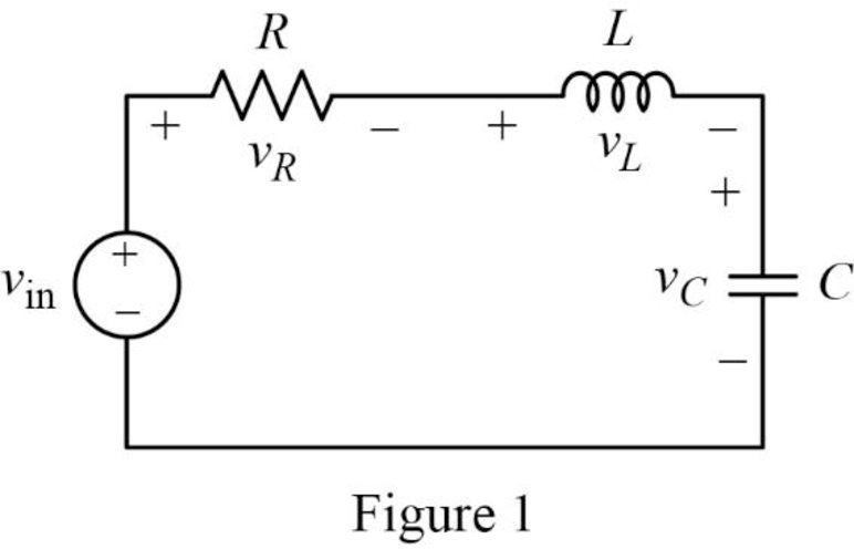
The Figure 1 is redrawn as impedance circuit in s-domain in Figure 2 using the equations (2), (3) and (4).
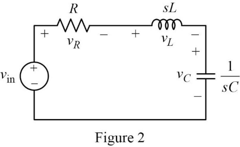
Write the general expression to calculate the transfer function of the circuit in Figure 2.
Here,
Apply Kirchhoff’s voltage law on Figure 2 to find
Rearrange the above equation to find
Substitute
Compare the above equation with the equation (1) to obtain the following values.
Rearrange the equation (6).
Rearrange the above equation to find
Rearrange the equation (7) to find
Substitute
Conclusion:
Thus, the value of
(b)
Find the values of inductor
(b)
Answer to Problem 15E
The value of inductor
Explanation of Solution
Given data:
The value of the resistor
The value of the resonant frequency
Calculation:
Case (i):
From part (a),
Substitute
Rearrange the above equation to find
Rearrange the above equation to find
Rearrange the equation (9).
Rearrange the above equation to find
Substitute
Rearrange the above equation to find
Take square root on both sides of the above equation to find
Substitute
Case (ii):
Substitute
Rearrange the above equation to find
Rearrange the above equation to find
Substitute
Rearrange the above equation to find
Take square root on both sides of the above equation to find
Substitute
Case (iii):
Substitute
Rearrange the above equation to find
Rearrange the above equation to find
Substitute
Rearrange the above equation to find
Take square root on both sides of the above equation to find
Substitute
Conclusion:
Thus, the value of inductor
(c)
Construct the magnitude Bode plots for the three cases
(c)
Explanation of Solution
Calculation:
Simplify the equation (1) to find
Case (i):
Substitute
Case (ii):
Substitute
Case (iii):
Substitute
The equations (15), (16) and (17) are the transfer function of the given series RLC circuit at three different cases
The MATLAB code is given below to sketch the magnitude Bode plots for the three cases using the equations (15), (16) and (17).
MATLAB Code:
clc;
clear all;
close all;
sys1=tf([(4*10^6)],[1 400 (4*10^6)]);
sys2=tf([(4*10^6)],[1 2000 (4*10^6)]);
sys3=tf([(4*10^6)],[1 4000 (4*10^6)]);
bode(sys1,sys2,sys3)
legend({'sys1','sys2','sys3'},'Location','best')
Output:
The MATLAB output Bode plot of the three transfer functions is shown Figure 1.
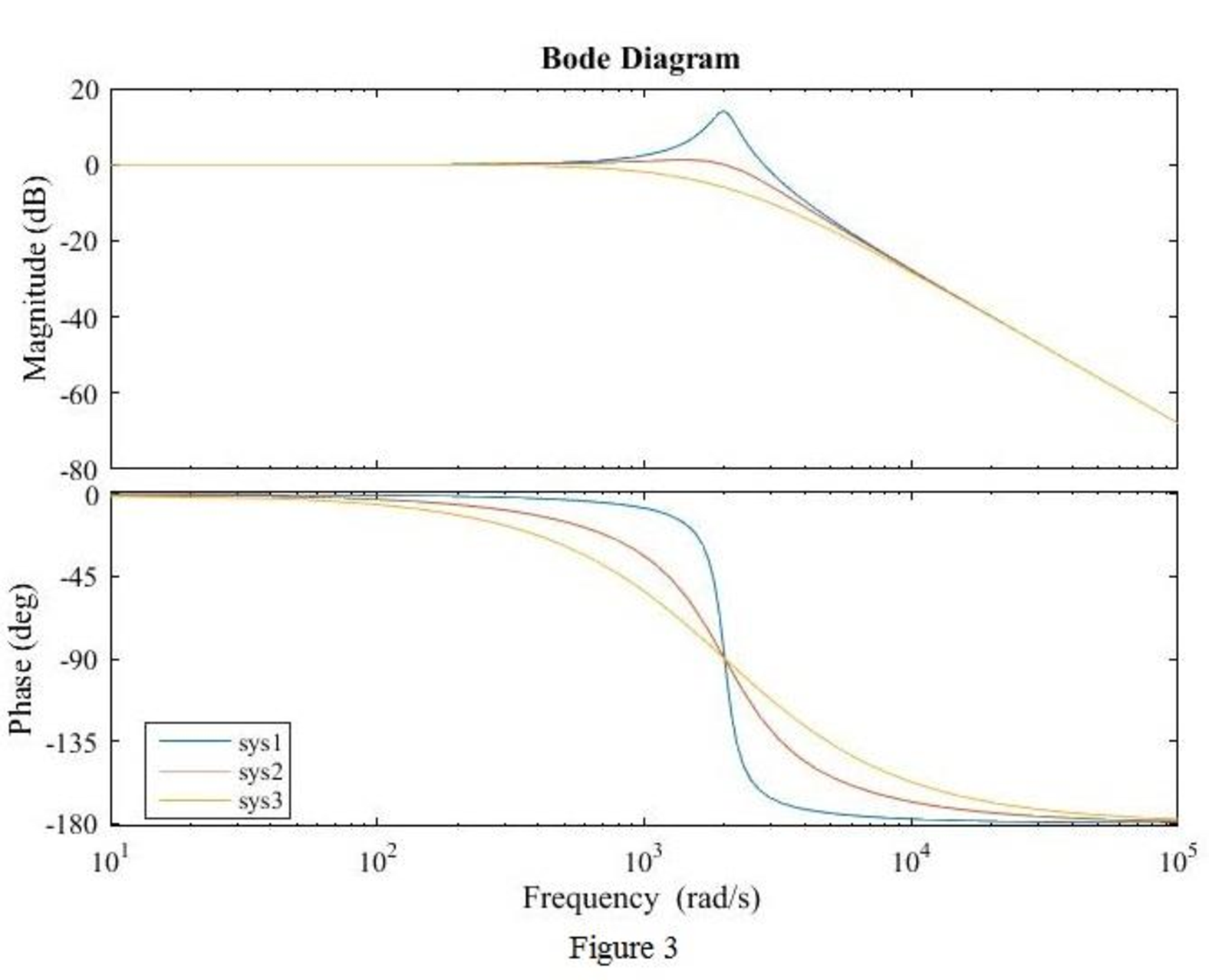
Conclusion:
Thus, the magnitude Bode plot for the three cases
Want to see more full solutions like this?
Chapter 15 Solutions
Loose Leaf for Engineering Circuit Analysis Format: Loose-leaf

- Refer to the block diagram below. If K = 14, determine the a) overall transfer function, b) natural frequency, c) damping ratio, d) settling time, e) peak time, ) percent overshoot, and g) rise time. s+6 R K s2 + 6s + 8 s+4arrow_forward11. Draw phase lead compensator electrical network and find its transfer function. (OR) 12. Obtain the state space representation of the system whose transfer function is given 10 by Y(s) U(s) s+2s +14s +10arrow_forwardWhat is the natural frequency of the system with the following transfer function? a) ₁₁ = 2 n b) @₁=16 n c) @₂₁ = √√32 n d) @₁₂₁ = 4 n X(s) 32 F(s) 2s² +4s+32arrow_forward
- C/2 C/2 + 2R 2R + V R Vo in out (a) Find the state-space model of the system. (b) Find the transfer function of the system from the state-space model.arrow_forwardA series RLC circuit has the following component values: R = 11 ohms, L=1 H, and C= 33.06 mF, the roots of the transfer function of this circuit would be: A. real and distinct О В. гeal and rереated O C. None of the other choices are correct O D. Complex O E. real and complexarrow_forwardQ2. For the s-domain circuit shown in Figure 2, Find (a) the transfer function H(s) = (b) the impulse response h(t). VI 202 ww 294/s-Vo Figure 2arrow_forward
- Parameters of the following transfer function is given as: k=5.1, a=3.5, b=3.4, and c=6, determine the Magnitude of steady-state response of the system to a step input H=6.5. (please keep four digits after decimal point) TF as+bs+carrow_forward| H.W. (2): Find the circuits diagram for every transfer function below: a. b. Vi 1 RcD +1 RcD LcD² + RcD+1 Vo ► Vrarrow_forwardClassify the response of the system and write ihe transfer function of the step response: (t) = A+ Be 161 cos(12t + p) %3Darrow_forward
- 2. Consider the following transfer function model W(s) = 1 s5 +10s +35³ +50s² +24s +11 Use the Hurwitz criterion to determine if the closed-loop system is stable: W(s)arrow_forwardAn LTI system is described by the following transfer function H(s). In MATLAB Live Script, compute and plot the system's frequency response consisting of a magnitude response in dB and a phase response in degrees as a function of angular frequency. 0.2s² + 0.3s +1 H(s) s2 + 0.4s + 1arrow_forwardPlease answer these questions and do not reject them 1. Obtain the differential equation with O(t) as the input and 0.(t) as the output. 2. Draw the block diagram of the system with the transfer function of each component. 3. Obtain the transfer function of the system 4. Explain what you need to do to fix the problem.arrow_forward
 Introductory Circuit Analysis (13th Edition)Electrical EngineeringISBN:9780133923605Author:Robert L. BoylestadPublisher:PEARSON
 Delmar's Standard Textbook Of ElectricityElectrical EngineeringISBN:9781337900348Author:Stephen L. HermanPublisher:Cengage Learning
 Programmable Logic ControllersElectrical EngineeringISBN:9780073373843Author:Frank D. PetruzellaPublisher:McGraw-Hill Education
 Fundamentals of Electric CircuitsElectrical EngineeringISBN:9780078028229Author:Charles K Alexander, Matthew SadikuPublisher:McGraw-Hill Education
 Electric Circuits. (11th Edition)Electrical EngineeringISBN:9780134746968Author:James W. Nilsson, Susan RiedelPublisher:PEARSON
 Engineering ElectromagneticsElectrical EngineeringISBN:9780078028151Author:Hayt, William H. (william Hart), Jr, BUCK, John A.Publisher:Mcgraw-hill Education,