
Loose Leaf for Engineering Circuit Analysis Format: Loose-leaf
9th Edition
ISBN: 9781259989452
Author: Hayt
Publisher: Mcgraw Hill Publishers
expand_more
expand_more
format_list_bulleted
Videos
Textbook Question
Chapter 15, Problem 47E
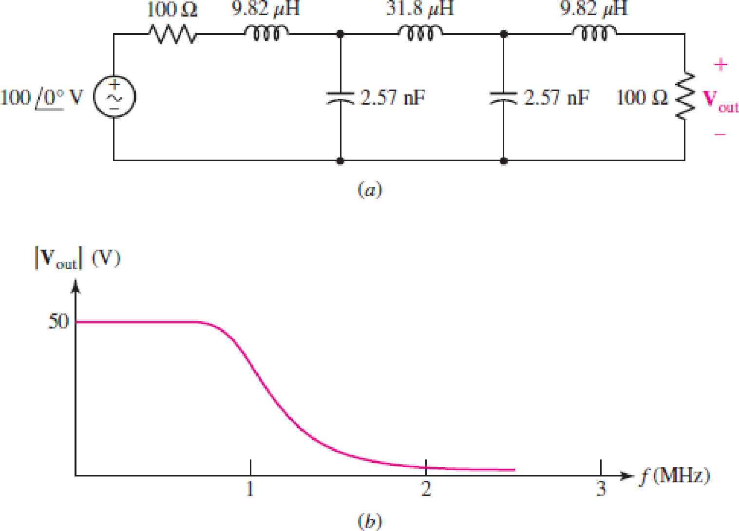
The filter shown in Fig. 15.66a has the response curve shown in Fig. 15.66b. (a) Scale the filter so that it operates between a 50 Ω source and a 50 Ω load and has a cutoff frequency of 20 kHz. (b) Draw the new response curve.
Expert Solution & Answer
Want to see the full answer?
Check out a sample textbook solution
Students have asked these similar questions
For the following filters' circuits:
a) Find and draw H(j@)
b) Specify what type of filter is this using qualitative analysis
Consider a cutoff (corner) frequency of 5 kHz.
2. Choose a type of high pass or low pass filter, and design the filter by choosing the
values of R and C to achieve the proper frequency. consider values
commercials for resistors. Calculate C regardless of whether it is a value
commercial or not.
15.5 What is the bandwidth of a band-pass filter whose critical frequencies are 3.2kHz and 3.9kHz? What is the
Q of this filter?
Chapter 15 Solutions
Loose Leaf for Engineering Circuit Analysis Format: Loose-leaf
Ch. 15.1 - Write an expression for the transfer function of...Ch. 15.2 - Calculate HdB at = 146 rad/s if H(s) equals (a)...Ch. 15.2 - Prob. 3PCh. 15.2 - Draw the Bode phase plot for the transfer function...Ch. 15.2 - Construct a Bode magnitude plot for H(s) equal to...Ch. 15.2 - Draw the Bode phase plot for H(s) equal to (a)...Ch. 15.2 - Prob. 7PCh. 15.3 - A parallel resonant circuit is composed of the...Ch. 15.3 - Prob. 9PCh. 15.4 - A marginally high-Q parallel resonant circuit has...
Ch. 15.5 - A series resonant circuit has a bandwidth of 100...Ch. 15.6 - Referring to the circuit of Fig. 15.25a, let R1 =...Ch. 15.6 - Prob. 13PCh. 15.6 - Prob. 14PCh. 15.6 - The series combination of 10 and 10 nF is in...Ch. 15.7 - A parallel resonant circuit is defined by C = 0.01...Ch. 15.8 - Design a high-pass filter with a cutoff frequency...Ch. 15.8 - Design a bandpass filter with a low-frequency...Ch. 15.8 - Design a low-pass filter circuit with a gain of 30...Ch. 15 - For the RL circuit in Fig. 15.52, (a) determine...Ch. 15 - For the RL circuit in Fig. 15.52, switch the...Ch. 15 - Examine the series RLC circuit in Fig. 15.53, with...Ch. 15 - For the circuit in Fig. 15.54, (a) derive an...Ch. 15 - For the circuit in Fig. 15.55, (a) derive an...Ch. 15 - For the circuit in Fig. 15.56, (a) determine the...Ch. 15 - For the circuit in Fig. 15.57, (a) determine the...Ch. 15 - Sketch the Bode magnitude and phase plots for the...Ch. 15 - Use the Bode approach to sketch the magnitude of...Ch. 15 - If a particular network is described by transfer...Ch. 15 - Use MATLAB to plot the magnitude and phase Bode...Ch. 15 - Determine the Bode magnitude plot for the...Ch. 15 - Determine the Bode magnitude and phase plot for...Ch. 15 - Prob. 15ECh. 15 - Prob. 16ECh. 15 - For the circuit of Fig. 15.56, construct a...Ch. 15 - Construct a magnitude and phase Bode plot for the...Ch. 15 - For the circuit in Fig. 15.54, use LTspice to...Ch. 15 - For the circuit in Fig. 15.55, use LTspice to...Ch. 15 - Prob. 21ECh. 15 - A certain parallel RLC circuit is built using...Ch. 15 - A parallel RLC network is constructed using R = 5...Ch. 15 - Prob. 24ECh. 15 - Delete the 2 resistor in the network of Fig....Ch. 15 - Delete the 1 resistor in the network of Fig....Ch. 15 - Prob. 28ECh. 15 - Prob. 29ECh. 15 - Prob. 30ECh. 15 - A parallel RLC network is constructed with a 200 H...Ch. 15 - Prob. 32ECh. 15 - A parallel RLC circuit is constructed such that it...Ch. 15 - Prob. 34ECh. 15 - Prob. 35ECh. 15 - An RLC circuit is constructed using R = 5 , L = 20...Ch. 15 - Prob. 37ECh. 15 - Prob. 38ECh. 15 - For the network of Fig. 15.25a, R1 = 100 , R2 =...Ch. 15 - Assuming an operating frequency of 200 rad/s, find...Ch. 15 - Prob. 41ECh. 15 - Prob. 42ECh. 15 - For the circuit shown in Fig. 15.64, the voltage...Ch. 15 - Prob. 44ECh. 15 - Prob. 45ECh. 15 - Prob. 46ECh. 15 - The filter shown in Fig. 15.66a has the response...Ch. 15 - Prob. 48ECh. 15 - Examine the filter for the circuit in Fig. 15.68....Ch. 15 - Examine the filter for the circuit in Fig. 15.69....Ch. 15 - (a)Design a high-pass filter with a corner...Ch. 15 - (a) Design a low-pass filter with a break...Ch. 15 - Prob. 53ECh. 15 - Prob. 54ECh. 15 - Design a low-pass filter characterized by a...Ch. 15 - Prob. 56ECh. 15 - The circuit in Fig. 15.70 is known as a notch...Ch. 15 - (a) Design a two-stage op amp filter circuit with...Ch. 15 - Design a circuit which removes the entire audio...Ch. 15 - Prob. 61ECh. 15 - If a high-pass filter is required having gain of 6...Ch. 15 - (a) Design a second-order high-pass Butterworth...Ch. 15 - Design a fourth-order high-pass Butterworth filter...Ch. 15 - (a) Design a Sallen-Key low-pass filter with a...Ch. 15 - (a) Design a Sallen-Key low-pass filter with a...Ch. 15 - A piezoelectric sensor has an equivalent circuit...Ch. 15 - Design a parallel resonant circuit for an AM radio...Ch. 15 - The network of Fig. 15.72 was implemented as a...Ch. 15 - Determine the effect of component tolerance on the...
Additional Engineering Textbook Solutions
Find more solutions based on key concepts
Assume a telephone signal travels through a cable at two-thirds the speed of light. How long does it take the s...
Electric Circuits (10th Edition)
Find I0 and I1 in the circuit in Fig.P2.12.
Basic Engineering Circuit Analysis
Analog Voltmeter Design Figure P2-98(a) shows a voltmeter circuit consisting of a D'Arsonval meter, two series ...
ANALYSIS+DESIGN OF LINEAR CIRCUITS(LL)
Electric power systems provide energy in a variety of commercial and industrial settings. Make a list of system...
Principles and Applications of Electrical Engineering
A constant voltage of 10V is applied to a 50H inductance, as shown in Figure P3.51 Figure P3 51 The current in ...
Electrical Engineering: Principles & Applications (7th Edition)
Write the nodal equations for the network of Fig. 8.137 using the general approach. Find the nodal voltages usi...
Introductory Circuit Analysis (13th Edition)
Knowledge Booster


Learn more about
Need a deep-dive on the concept behind this application? Look no further. Learn more about this topic, electrical-engineering and related others by exploring similar questions and additional content below.Similar questions
- a) According to the circuit in the Figure 1: I Write down the type of this filter (Output taken over C, as dots symbolize). II. Calculate the cut-off frequency in Hz. III. Calculate V, in magnitude when the source voltage has frequencies of 0.4, 0.8, 1.6, 4, 8 kHz. V,(t) = 18 V (peak-to-peak) R= 22 k2 V,(1) =18V (A V,(1) C=0,05 µF Figure 1arrow_forward(c) Design a series RLC bandpass filter with cutoff frequencies fc₁ = 1 KHz, fcz = 20 KHz, using a 100 resistor. Draw the circuit and label all the components, including circuit values, including input and output. Also draw the magnitude and phase plots for the filter. Amplitude [dB] 50 40 30- Phase [°] 10 of- -10... -20... -30- -40- -50 0.1 180 135 90 C 45 of -45- -90 -135- -180 0.1 1 1 10 10 100 100 1000 1000 10,000 Freq. (Hz) 10,000 Freq. (Hz)arrow_forward+ V1 AC 1 R1 200 R2 100 C1 1µF .ac dec 10 1 100k 1. What type of filter is pictured above? (Highpass Lowpass Bandpass) 2. What is the corner frequency of this filter? 3. Sketch the magnitude plot of a Bode plot for this filter. 4. Sketch the phase plot of a Bode plot for this filter. 5. What is the approximate gain of this filter at 10KHz. Answer in dB. + Voutarrow_forward
- Q1. For the following filter circuit in Figure 1: find the transfer function H(s) and draw the magnitude of H(s) versus o. Also, specify the type of filter and find the cutoff frequency a and the filter band width. 100 UF 50 mH Vin ) 1 ohm V. Figure 1 Q2. For the following filter circuit in Figure 2: find the transfer function H(s) and draw the magnitude of H(s) versus w. Also, specify the type of filter and find the cutoff frequency o and the filter band width. 100 UF 5 ohm 50 mH Vin 1 ohm V. Figure 2 Q4. For the following filter circuit in Figure 4: find the transfer function H(s) at Vol and Ve2, and draw the magnitude of H(s) versus o. +Vel - 5 ohm Vin 10 uH S UF V Figure 4arrow_forwardProblem 5. ldentify the circuit shown below with a check mark next to the correct answer 1. High-Q band- pass filter Wien Bridge Oscillator 3. High pass filter 4. Colpitts Oscillator 5. Two pole low pass filter Six pole high pass filter In the answer which you selected above write the equation for -3dB cutoff frequency in terms of the com 2. 6. 7. shown. Answer: R, R2 VN w VOUT C, al, nooroductionarrow_forward15.5 shows the Bode magnitude plot of a high-pass filter. Using theactive high-pass filter circuit in 15.4, calculate values of R1 and R2 thatproduce the desired magnitude response. Use a 0.1 μF capacitor. If a 10 kΩload resistor is added to this filter, how will the magnitude response change?arrow_forward
- Give the other types of high-pass filters. Draw the circuit and frequency response of each.arrow_forwardGive the other types of low-pass filters. Draw the circuit and frequency response of each.arrow_forwardQ5/A: For the circuit shown below, find the transfer function vo/vs. Show that the circuit is a lowpass passive filter 1 H 120/0° V rms m €0.25 2 IF= Q5/B: In the ideal transformer circuit shown below, determine the average power delivered the load 30+j1202 rele 1000 turns +0 200 turns 20-140arrow_forward
- VS+ -SA V1 5 V2 5 .ac dec 100 1 1Meg lib LM741.mod VIN V3 R1 C1 1.3k 0.12μ AC 1 Figure. Active Band Pass Filter R2 1.3k C2 0.12μ Imax -VS+ -SA U1 VOUT LM741/NS Provide the following expressions or values as required: VOUT VIN ) Expression for the maximum gain/magnitude G = ) Expression for the natural frequency fo and its corresponding value ) Expression for selectivity Q and its corresponding value and its corresponding valuearrow_forwardAn RL low-pass filter is shown in the figure. Its purpose is to attenuate higher frequencies while allowing lower frequencies to pass through. A 920-Hz sine-wave signal with rms amplitude of Vrms = 2.1 V is fed into the filter. The values of the components are R = 0.57 Ω and L = 110 μH. A) Find the output rms voltage, in volts. B) By what angle, in degrees, does the output voltage lag the input voltage?arrow_forwardParameter Value Gain, AV 30 dB Resistor, R1 1.5 kΩ Capacitor, C 3.35 uF 1. Figure depicts a first order low pass filter and Table tabulates parameters ultised to construct the filter. In the design, R1||R2. Calculate the bandwith of the filter. 2. Describe the condition of unity gain in an amplifier and determine voltage output, VO,if voltage input, V1, is 2V for a non-inverting amplifier 3. Construct an equation relating the input (Vin) and output (Vout) of an inverting amplifier.The conditioning circuit has input range between 10 mV to 110 mV which resultingoutput between 0V to 5V.arrow_forward
arrow_back_ios
SEE MORE QUESTIONS
arrow_forward_ios
Recommended textbooks for you
 Introductory Circuit Analysis (13th Edition)Electrical EngineeringISBN:9780133923605Author:Robert L. BoylestadPublisher:PEARSON
 Delmar's Standard Textbook Of ElectricityElectrical EngineeringISBN:9781337900348Author:Stephen L. HermanPublisher:Cengage Learning
 Programmable Logic ControllersElectrical EngineeringISBN:9780073373843Author:Frank D. PetruzellaPublisher:McGraw-Hill Education
 Fundamentals of Electric CircuitsElectrical EngineeringISBN:9780078028229Author:Charles K Alexander, Matthew SadikuPublisher:McGraw-Hill Education
 Electric Circuits. (11th Edition)Electrical EngineeringISBN:9780134746968Author:James W. Nilsson, Susan RiedelPublisher:PEARSON
 Engineering ElectromagneticsElectrical EngineeringISBN:9780078028151Author:Hayt, William H. (william Hart), Jr, BUCK, John A.Publisher:Mcgraw-hill Education,
Introductory Circuit Analysis (13th Edition)
Electrical Engineering
ISBN:9780133923605
Author:Robert L. Boylestad
Publisher:PEARSON
Delmar's Standard Textbook Of Electricity
Electrical Engineering
ISBN:9781337900348
Author:Stephen L. Herman
Publisher:Cengage Learning
Programmable Logic Controllers
Electrical Engineering
ISBN:9780073373843
Author:Frank D. Petruzella
Publisher:McGraw-Hill Education
Fundamentals of Electric Circuits
Electrical Engineering
ISBN:9780078028229
Author:Charles K Alexander, Matthew Sadiku
Publisher:McGraw-Hill Education
Electric Circuits. (11th Edition)
Electrical Engineering
ISBN:9780134746968
Author:James W. Nilsson, Susan Riedel
Publisher:PEARSON
Engineering Electromagnetics
Electrical Engineering
ISBN:9780078028151
Author:Hayt, William H. (william Hart), Jr, BUCK, John A.
Publisher:Mcgraw-hill Education,
Pressure Sensors with Display; Author: Balluff Worldwide;https://www.youtube.com/watch?v=HqAV2xjCLxE;License: Standard Youtube License