
Loose Leaf for Engineering Circuit Analysis Format: Loose-leaf
9th Edition
ISBN: 9781259989452
Author: Hayt
Publisher: Mcgraw Hill Publishers
expand_more
expand_more
format_list_bulleted
Concept explainers
Videos
Textbook Question
Chapter 15, Problem 26E
Delete the 2 Ω resistor in the network of Fig. 15.58 and determine (a) the magnitude of the input impedance at resonance and (b) the resonant frequency.
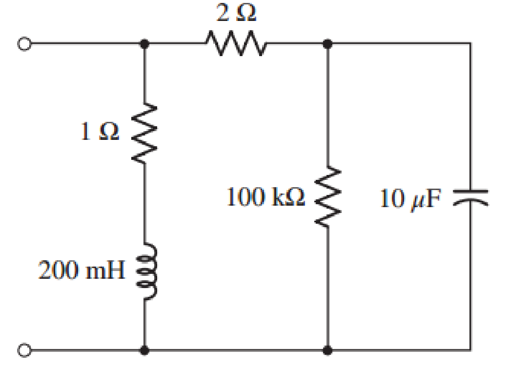
FIGURE. 15.58
Expert Solution & Answer
Want to see the full answer?
Check out a sample textbook solution
Students have asked these similar questions
Q5)
2) Use the RLC circuit below to answer the following questions.
R1
L1
zt √FL C
(18)
NS
= R
10Vrms
*15= 10M
10
-= 1/5 =
1/2 = 0.66
Vs
1 = 0.66 K√2 = 0.933
For the above circuit, determine:
15Ω
2mH
C1
H
50pF
a) The resonant frequency in kHz.
b) The voltage drop across the resistor at the resonant frequency.
c) Determine the rms and peak values of the circuit current at the resonant frequency
In a series RLC circuit that is operating above the resonant frequency, the
current
Leads the applied voltage
Lags the applied voltage
Is zero
Is in phase with the applied voltage
The mathematical relation between impedance and admittance locus are
Mirrored
Reciprocally O
Opposite
Inversely
The non-sinusoidal waves which represent a sum of infinite number of harmonic
waves can affect on
All-of-them
Electronic Devices and Circuits
Power system
Communications
هذا السؤال مطلوب
1. A parallel R-L-C circuit is fed by a constant
current source of variable frequency. The circuit
resonates at 100 kHz and the Q-factor
measured at this frequency is 5. Find the
frequencies at which the amplitude of the
voltage across the circuit falls to (a) 70.7% (b)
50% of the resonant frequency amplitude. [(a)
90.5 kHz ; 110.5 kHz (b) 84.18 kHz ; 118.8 kHz]
Chapter 15 Solutions
Loose Leaf for Engineering Circuit Analysis Format: Loose-leaf
Ch. 15.1 - Write an expression for the transfer function of...Ch. 15.2 - Calculate HdB at = 146 rad/s if H(s) equals (a)...Ch. 15.2 - Prob. 3PCh. 15.2 - Draw the Bode phase plot for the transfer function...Ch. 15.2 - Construct a Bode magnitude plot for H(s) equal to...Ch. 15.2 - Draw the Bode phase plot for H(s) equal to (a)...Ch. 15.2 - Prob. 7PCh. 15.3 - A parallel resonant circuit is composed of the...Ch. 15.3 - Prob. 9PCh. 15.4 - A marginally high-Q parallel resonant circuit has...
Ch. 15.5 - A series resonant circuit has a bandwidth of 100...Ch. 15.6 - Referring to the circuit of Fig. 15.25a, let R1 =...Ch. 15.6 - Prob. 13PCh. 15.6 - Prob. 14PCh. 15.6 - The series combination of 10 and 10 nF is in...Ch. 15.7 - A parallel resonant circuit is defined by C = 0.01...Ch. 15.8 - Design a high-pass filter with a cutoff frequency...Ch. 15.8 - Design a bandpass filter with a low-frequency...Ch. 15.8 - Design a low-pass filter circuit with a gain of 30...Ch. 15 - For the RL circuit in Fig. 15.52, (a) determine...Ch. 15 - For the RL circuit in Fig. 15.52, switch the...Ch. 15 - Examine the series RLC circuit in Fig. 15.53, with...Ch. 15 - For the circuit in Fig. 15.54, (a) derive an...Ch. 15 - For the circuit in Fig. 15.55, (a) derive an...Ch. 15 - For the circuit in Fig. 15.56, (a) determine the...Ch. 15 - For the circuit in Fig. 15.57, (a) determine the...Ch. 15 - Sketch the Bode magnitude and phase plots for the...Ch. 15 - Use the Bode approach to sketch the magnitude of...Ch. 15 - If a particular network is described by transfer...Ch. 15 - Use MATLAB to plot the magnitude and phase Bode...Ch. 15 - Determine the Bode magnitude plot for the...Ch. 15 - Determine the Bode magnitude and phase plot for...Ch. 15 - Prob. 15ECh. 15 - Prob. 16ECh. 15 - For the circuit of Fig. 15.56, construct a...Ch. 15 - Construct a magnitude and phase Bode plot for the...Ch. 15 - For the circuit in Fig. 15.54, use LTspice to...Ch. 15 - For the circuit in Fig. 15.55, use LTspice to...Ch. 15 - Prob. 21ECh. 15 - A certain parallel RLC circuit is built using...Ch. 15 - A parallel RLC network is constructed using R = 5...Ch. 15 - Prob. 24ECh. 15 - Delete the 2 resistor in the network of Fig....Ch. 15 - Delete the 1 resistor in the network of Fig....Ch. 15 - Prob. 28ECh. 15 - Prob. 29ECh. 15 - Prob. 30ECh. 15 - A parallel RLC network is constructed with a 200 H...Ch. 15 - Prob. 32ECh. 15 - A parallel RLC circuit is constructed such that it...Ch. 15 - Prob. 34ECh. 15 - Prob. 35ECh. 15 - An RLC circuit is constructed using R = 5 , L = 20...Ch. 15 - Prob. 37ECh. 15 - Prob. 38ECh. 15 - For the network of Fig. 15.25a, R1 = 100 , R2 =...Ch. 15 - Assuming an operating frequency of 200 rad/s, find...Ch. 15 - Prob. 41ECh. 15 - Prob. 42ECh. 15 - For the circuit shown in Fig. 15.64, the voltage...Ch. 15 - Prob. 44ECh. 15 - Prob. 45ECh. 15 - Prob. 46ECh. 15 - The filter shown in Fig. 15.66a has the response...Ch. 15 - Prob. 48ECh. 15 - Examine the filter for the circuit in Fig. 15.68....Ch. 15 - Examine the filter for the circuit in Fig. 15.69....Ch. 15 - (a)Design a high-pass filter with a corner...Ch. 15 - (a) Design a low-pass filter with a break...Ch. 15 - Prob. 53ECh. 15 - Prob. 54ECh. 15 - Design a low-pass filter characterized by a...Ch. 15 - Prob. 56ECh. 15 - The circuit in Fig. 15.70 is known as a notch...Ch. 15 - (a) Design a two-stage op amp filter circuit with...Ch. 15 - Design a circuit which removes the entire audio...Ch. 15 - Prob. 61ECh. 15 - If a high-pass filter is required having gain of 6...Ch. 15 - (a) Design a second-order high-pass Butterworth...Ch. 15 - Design a fourth-order high-pass Butterworth filter...Ch. 15 - (a) Design a Sallen-Key low-pass filter with a...Ch. 15 - (a) Design a Sallen-Key low-pass filter with a...Ch. 15 - A piezoelectric sensor has an equivalent circuit...Ch. 15 - Design a parallel resonant circuit for an AM radio...Ch. 15 - The network of Fig. 15.72 was implemented as a...Ch. 15 - Determine the effect of component tolerance on the...
Additional Engineering Textbook Solutions
Find more solutions based on key concepts
A constant voltage of 10V is applied to a 50H inductance, as shown in Figure P3.51 Figure P3 51 The current in ...
Electrical Engineering: Principles & Applications (7th Edition)
How many coulombs do 93.8 1016 electrons represent?
Principles Of Electric Circuits
The current source in the circuit shown generates the current pulse
Find (a) v (0); (b) the instant of time gr...
Electric Circuits. (11th Edition)
Find I0 and I1 in the circuit in Fig.P2.12.
Basic Engineering Circuit Analysis
Electric power systems provide energy in a variety of commercial and industrial settings. Make a list of system...
Principles and Applications of Electrical Engineering
Explain the main function of each of the following major components of a PLC: a. Processor module (CPU) b. I/O ...
Programmable Logic Controllers
Knowledge Booster


Learn more about
Need a deep-dive on the concept behind this application? Look no further. Learn more about this topic, electrical-engineering and related others by exploring similar questions and additional content below.Similar questions
- A coil of resistance 25 and inductance 100 mH is connected in series with a capacitance of 0.12 µF across a 200 V, variable frequency supply. Calculate: a) The resonant frequency b) The current at resonance, and c) The factor by which the voltage across each reactance is greater than the supply voltage. ANS: (a) 1452.879 Hz (1.453 kHz) (b) 8 <0° A (c) 36.515arrow_forwardIn A Series Circuit, Figure 1 Finds The Following: 1. Find the value of inductor at resonance 2. coil and capacitor voltage at resonance :VL, VC Q factor at resonance 3. R1 6 Ohm 120 V/60 Hz/0 Deg 25 Ohm M^^^ R2 3 uF HH 20 mHarrow_forward1. Assume a parallel resonant circuit is constructed from a 200 µH inductor with 9.502 of resistance and a 1000 pF capacitor. a. What is the resonant frequency? b. What is the Q? What is the bandwidth? C. (Ctrl) Iarrow_forward
- Given the circuit, solve for 1. V,, V. and Ve 2. AC circuit current ( m) 3. Resonant frequency (F 4. AC circuit power 5. AC power factor (Cos e) (P) R 2 250 2 120 V L. 650 mH 60 Hz 3 1.5 µFarrow_forwardThe circuit shown in figure is in series resonance at frequency fc Hz. The value of Vc in volts is 10 S2 www 0.1 H m 1v fcHz 0.1 uF Vo مثال V.arrow_forwardQ.5: a) Correct any five of the following sentences using suitable scientific phrases. 1. At any resonant circuit the input impedance is reactance (X or Xc). 2. The locus of inductive load is a vector in the 2nd quadrant. 3. Any non-sinusoidal wave can be represented by a sum of sine waves with harmonic frequencies. 4. The power dissipated in a resistance is equal to 21'R in non-sinusoidal input signal. 5. In transient circuit when the switch is closed for a long time the inductor behaves as an open circuit. 6. The DC input voltage could be represented by Vs in Laplace methods. 7. The electrical energy is stored in the resistance. (15 marks]arrow_forward
- In an LCR circuit, L = 10 mH, C = 0.1μF and R = 200 2. Is the circuit oscillatory? If so, what is its frequency?arrow_forwardH.W: A resistor of resistance R=1000 2 is maintained at 17 °C and it shunted by 100 µH inductor. Determine the rms noise voltage across the inductor over a frequency bandwidth of: Ans: 182 x10-9 volt i) ii) iii) 15.9 kHz Ans: 9.22 x10⁻⁸ volt Ans: 2.34 x10⁻⁶ volt 159 kHz 1590 kHzarrow_forwardA supply voltage of 3 V is applied to a series R–L–C circuit whose resistance is 12 ohms , inductance is 7.5 mH and capacitance is 0.5µF. Determine (a) the current flowing at resonance, (b) the current flowing at a frequency 2.5% below the resonant frequency and (c) the impedance of the circuit when the frequency is 1% lower than the resonant frequency.arrow_forward
- 1. The mathematical expression of the frequency spectrum of a general FM signal shows that it has technically a limited bandwidth a wide bandwidth an infinite bandwidth narrow bandwidth none of the choices 2. The break frequency for commercial FM broadcast of the preemphasis and deemphasis network is 2.122 kHz 2122 kHz 75 kHz 75 Hz none of the choicesarrow_forwardThe current at resonance in a series L– C–R circuit is 100µA. If the applied voltage is 2 mV at a frequency of 200 kHz, and the circuit inductance is 50µH, find the circuit resistance, and the circuit capacitance.arrow_forwardDetermine the total impedance as the frequency approaches 1) infinity 2)zero 3) 159.15 Hz (resonant, impedance turns into a real value) When does LC act as an open and short circuitarrow_forward
arrow_back_ios
SEE MORE QUESTIONS
arrow_forward_ios
Recommended textbooks for you
 Introductory Circuit Analysis (13th Edition)Electrical EngineeringISBN:9780133923605Author:Robert L. BoylestadPublisher:PEARSON
 Delmar's Standard Textbook Of ElectricityElectrical EngineeringISBN:9781337900348Author:Stephen L. HermanPublisher:Cengage Learning
 Programmable Logic ControllersElectrical EngineeringISBN:9780073373843Author:Frank D. PetruzellaPublisher:McGraw-Hill Education
 Fundamentals of Electric CircuitsElectrical EngineeringISBN:9780078028229Author:Charles K Alexander, Matthew SadikuPublisher:McGraw-Hill Education
 Electric Circuits. (11th Edition)Electrical EngineeringISBN:9780134746968Author:James W. Nilsson, Susan RiedelPublisher:PEARSON
 Engineering ElectromagneticsElectrical EngineeringISBN:9780078028151Author:Hayt, William H. (william Hart), Jr, BUCK, John A.Publisher:Mcgraw-hill Education,
Introductory Circuit Analysis (13th Edition)
Electrical Engineering
ISBN:9780133923605
Author:Robert L. Boylestad
Publisher:PEARSON
Delmar's Standard Textbook Of Electricity
Electrical Engineering
ISBN:9781337900348
Author:Stephen L. Herman
Publisher:Cengage Learning
Programmable Logic Controllers
Electrical Engineering
ISBN:9780073373843
Author:Frank D. Petruzella
Publisher:McGraw-Hill Education
Fundamentals of Electric Circuits
Electrical Engineering
ISBN:9780078028229
Author:Charles K Alexander, Matthew Sadiku
Publisher:McGraw-Hill Education
Electric Circuits. (11th Edition)
Electrical Engineering
ISBN:9780134746968
Author:James W. Nilsson, Susan Riedel
Publisher:PEARSON
Engineering Electromagnetics
Electrical Engineering
ISBN:9780078028151
Author:Hayt, William H. (william Hart), Jr, BUCK, John A.
Publisher:Mcgraw-hill Education,
Understanding Amplitude Modulation; Author: Rohde Schwarz;https://www.youtube.com/watch?v=I46eP8uZh_Y;License: Standard Youtube License