
Videos
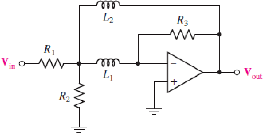
For the circuit in Fig. 15.57, (a) determine the transfer function H(s) = Vout/Vin in terms of circuit parameters R1, R2, R3, L1, and L2; (b) determine the magnitude and phase of the transfer function at ω = 0, 3 × 10³ rad/s, and as ω → ∞ for the case where circuit values are R1 = 2 kΩ, R2 = 2 kΩ, R3 = 20 kΩ, L1 = 2 H, and L2 = 2 H.
FIGURE 15.57
(a)
The transfer function
Answer to Problem 7E
The transfer function
Explanation of Solution
Given data:
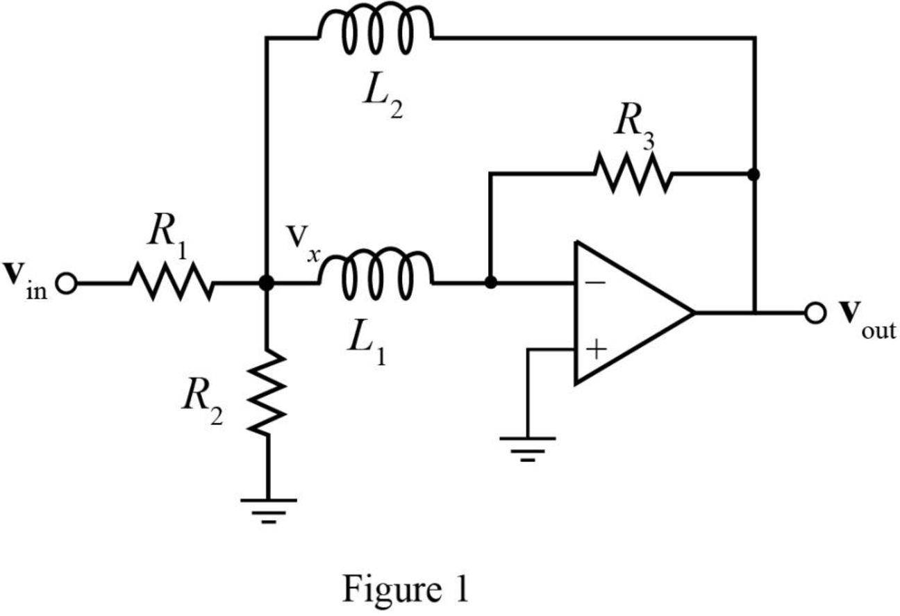
The required diagram is shown in Figure 1.
Calculation:
Assign the node intersecting the two resistors
The KCL equation at node
The KCL equation at node
Here,
Simplifying the equation (2) as,
The transfer function
Substitute
Substitute
Conclusion:
Therefore, the transfer function
(b)
The magnitude of transfer function
Answer to Problem 7E
The magnitude of transfer function
Explanation of Solution
Given data:
The resistance
The resistance
The resistance
The inductance
The inductance
The angular frequency
The angular frequency
The angular frequency
Calculation:
The conversion of
The conversion of
The conversion of
The magnitude of transfer function
The phase of transfer function
Substitute
Substitute
The magnitude of transfer function
The phase of transfer function
Substitute
Substitute
The magnitude of transfer function
The phase of transfer function
Substitute
Substitute
Conclusion:
Therefore, the magnitude of transfer function
Want to see more full solutions like this?
Chapter 15 Solutions
Loose Leaf for Engineering Circuit Analysis Format: Loose-leaf
Additional Engineering Textbook Solutions
Fundamentals of Applied Electromagnetics (7th Edition)
Engineering Electromagnetics
ELECTRICITY FOR TRADES (LOOSELEAF)
Introductory Circuit Analysis (13th Edition)
ANALYSIS+DESIGN OF LINEAR CIRCUITS(LL)
Programmable Logic Controllers


- An LTI system is described by the following transfer function H(s). In MATLAB Live Script, compute and plot the system's frequency response consisting of a magnitude response in dB and a phase response in degrees as a function of angular frequency. 0.2s² + 0.3s +1 H(s) s2 + 0.4s + 1arrow_forward2. For the following circuit: a. Determine the transfer function H(jo) (Show all your work). b. Sketch |H(jo) | c. Calculate the center frequency, upper and lower cutoff frequencies d. Calculate and bandwidth in Hz. e. Find vo(t) for the input of vi(t) = 2 cos(2n3000t) Solution: V:(t) R1 w 1 ΚΩ L1 100 mH C1 H 0.1 μF 1 ΚΩ V.(t) fe₁, fcz in Hz.arrow_forwardK(s+1) The cross-over frequency of the system with transfer function and phase margin equal to 50° is,arrow_forward
- In the complex plane, draw the PHASOR that corresponds to the transfer function for three cases: a) ω = ωC b) ω=10∗ωC c) ω=0.1∗ωC Put them on the same axes. Indicate the magnitude and the phase of the transfer function phasor. fc = 10KHz ωc = 2πfc This is for a passive low pass filter (one single resitor, one single capacitor) Please give an explanation if possible.arrow_forwardQuestion # 1 a) A certain filter has the following transfer function. 1500 H(jw)= (jw +50)² Find the value of frequency at which the magnitude equal (0.5 Hmax) b) The following circuit represents a filter 1- find he transfer function H(jw) Vo(jw)/Vs(jw). 2- find the kind of the filter, center frequency, cutoff frequencies and quality factor Vin(t) R2 R1 + Vo(t)arrow_forwardWhat is the natural frequency of the system with the following transfer function? a) ₁₁ = 2 n b) @₁=16 n c) @₂₁ = √√32 n d) @₁₂₁ = 4 n X(s) 32 F(s) 2s² +4s+32arrow_forward
- 7 The Bode plot of the unknown linear dynamic system is given. Try to find the parameters 'k' and 'a' of the transfer function below: * . G (s) = s+a Boe Dagram Freuen O n Magntue -14 Systern Treguency adh 50 Magnitude Fre o1 Phase g115 Syten Pha 45 Fre an O k = 1, a = 1000 Ok = 1000, a = 20 O k = 5, a = 100 O k = 10, a = 50 (oleorgutenarrow_forwardThe OLTF of a system is 30,000 G(s) = s¹+67³ +1017s² +8637s+137257 What is the phase crossover frequency? What is the gain crossover frequency? What is the gain margin? What is the phase margin? dB degrees. rad/s rad/sarrow_forwardThe resonant frequency of the circuit shown below is 36 Mrad/s and its bandwidth is 97.3 krad/s. The maximum amplitude of the source current is 100 µA and the value of the resistance R is 100 kQ. The max. value of the capacitor current |Ic(@0)| in mA is i R L Vo O A. 3.70 B. 0.37 O C. 369.99 O D. 37.00 allarrow_forward
- a a llAsiacell A distorted signal of frequency fm is recovered from a sampled signal if the sampling frequency fs is: O fs = 2fm O fs 2fmarrow_forwardA series RLC circuit has the following component values: R = 6 ohms, L= 100 mH, and C= 11.1 mF, the roots of the transfer function of this circuit would be: O A. real and distinct O B. Complex O C. real and complex O D. real and repeated O E. None of the other choices are correctarrow_forwardFor the circuit shown, let R = (a) (b) (c) (d) 600 2, L = 50μH and C1 = C2 = 40 nF. Find the transfer function and plot poles and zeros. Find oo, fo, 0₁ and 02 BW, Q, and E. Plot the magnitude and phase responses of the transfer function. V₁ R ww atat V₂arrow_forward
 Introductory Circuit Analysis (13th Edition)Electrical EngineeringISBN:9780133923605Author:Robert L. BoylestadPublisher:PEARSON
 Delmar's Standard Textbook Of ElectricityElectrical EngineeringISBN:9781337900348Author:Stephen L. HermanPublisher:Cengage Learning
 Programmable Logic ControllersElectrical EngineeringISBN:9780073373843Author:Frank D. PetruzellaPublisher:McGraw-Hill Education
 Fundamentals of Electric CircuitsElectrical EngineeringISBN:9780078028229Author:Charles K Alexander, Matthew SadikuPublisher:McGraw-Hill Education
 Electric Circuits. (11th Edition)Electrical EngineeringISBN:9780134746968Author:James W. Nilsson, Susan RiedelPublisher:PEARSON
 Engineering ElectromagneticsElectrical EngineeringISBN:9780078028151Author:Hayt, William H. (william Hart), Jr, BUCK, John A.Publisher:Mcgraw-hill Education,