
Loose Leaf for Engineering Circuit Analysis Format: Loose-leaf
9th Edition
ISBN: 9781259989452
Author: Hayt
Publisher: Mcgraw Hill Publishers
expand_more
expand_more
format_list_bulleted
Videos
Textbook Question
Chapter 15, Problem 19E
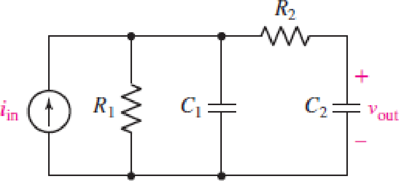
For the circuit in Fig. 15.54, use LTspice to construct a Bode plot of the frequency response for the case where R1 = 20 kΩ, R2 = 5 kΩ, C1 = 10 nF, and C2 = 40 nF. Use your plot to estimate locations of poles and zeros.
FIGURE 15.54
Expert Solution & Answer
Want to see the full answer?
Check out a sample textbook solution
Students have asked these similar questions
Given the series RLC circuit. If R=10 ohm, find the values of L and C such that the network will have a center frequency of 100 kHz and a
bandwidth of 1kHz. The output of the circuit is taken across series LC.
Select one:
O a. 1.59 mH and 1.59 nF
O b. 1.59 mH and 1.59 uF
1.59 H and 1.59 nF
1.59 uH and 1.59 uF
O C.
O d.
Calculate Resonance Frequency, Cutoff Frequencies, Bandwidth, and Quality Factor for
the RLC Circuit.
R3
470
R4
L3
C3
V1
2700
470uH 10NF
Passive filters are made of passive components, tuned to the harmonic frequencies that are to be
attenuated.
Show that a series LR circuit is a lowpass filter if the output is taken across the resistor.
Chapter 15 Solutions
Loose Leaf for Engineering Circuit Analysis Format: Loose-leaf
Ch. 15.1 - Write an expression for the transfer function of...Ch. 15.2 - Calculate HdB at = 146 rad/s if H(s) equals (a)...Ch. 15.2 - Prob. 3PCh. 15.2 - Draw the Bode phase plot for the transfer function...Ch. 15.2 - Construct a Bode magnitude plot for H(s) equal to...Ch. 15.2 - Draw the Bode phase plot for H(s) equal to (a)...Ch. 15.2 - Prob. 7PCh. 15.3 - A parallel resonant circuit is composed of the...Ch. 15.3 - Prob. 9PCh. 15.4 - A marginally high-Q parallel resonant circuit has...
Ch. 15.5 - A series resonant circuit has a bandwidth of 100...Ch. 15.6 - Referring to the circuit of Fig. 15.25a, let R1 =...Ch. 15.6 - Prob. 13PCh. 15.6 - Prob. 14PCh. 15.6 - The series combination of 10 and 10 nF is in...Ch. 15.7 - A parallel resonant circuit is defined by C = 0.01...Ch. 15.8 - Design a high-pass filter with a cutoff frequency...Ch. 15.8 - Design a bandpass filter with a low-frequency...Ch. 15.8 - Design a low-pass filter circuit with a gain of 30...Ch. 15 - For the RL circuit in Fig. 15.52, (a) determine...Ch. 15 - For the RL circuit in Fig. 15.52, switch the...Ch. 15 - Examine the series RLC circuit in Fig. 15.53, with...Ch. 15 - For the circuit in Fig. 15.54, (a) derive an...Ch. 15 - For the circuit in Fig. 15.55, (a) derive an...Ch. 15 - For the circuit in Fig. 15.56, (a) determine the...Ch. 15 - For the circuit in Fig. 15.57, (a) determine the...Ch. 15 - Sketch the Bode magnitude and phase plots for the...Ch. 15 - Use the Bode approach to sketch the magnitude of...Ch. 15 - If a particular network is described by transfer...Ch. 15 - Use MATLAB to plot the magnitude and phase Bode...Ch. 15 - Determine the Bode magnitude plot for the...Ch. 15 - Determine the Bode magnitude and phase plot for...Ch. 15 - Prob. 15ECh. 15 - Prob. 16ECh. 15 - For the circuit of Fig. 15.56, construct a...Ch. 15 - Construct a magnitude and phase Bode plot for the...Ch. 15 - For the circuit in Fig. 15.54, use LTspice to...Ch. 15 - For the circuit in Fig. 15.55, use LTspice to...Ch. 15 - Prob. 21ECh. 15 - A certain parallel RLC circuit is built using...Ch. 15 - A parallel RLC network is constructed using R = 5...Ch. 15 - Prob. 24ECh. 15 - Delete the 2 resistor in the network of Fig....Ch. 15 - Delete the 1 resistor in the network of Fig....Ch. 15 - Prob. 28ECh. 15 - Prob. 29ECh. 15 - Prob. 30ECh. 15 - A parallel RLC network is constructed with a 200 H...Ch. 15 - Prob. 32ECh. 15 - A parallel RLC circuit is constructed such that it...Ch. 15 - Prob. 34ECh. 15 - Prob. 35ECh. 15 - An RLC circuit is constructed using R = 5 , L = 20...Ch. 15 - Prob. 37ECh. 15 - Prob. 38ECh. 15 - For the network of Fig. 15.25a, R1 = 100 , R2 =...Ch. 15 - Assuming an operating frequency of 200 rad/s, find...Ch. 15 - Prob. 41ECh. 15 - Prob. 42ECh. 15 - For the circuit shown in Fig. 15.64, the voltage...Ch. 15 - Prob. 44ECh. 15 - Prob. 45ECh. 15 - Prob. 46ECh. 15 - The filter shown in Fig. 15.66a has the response...Ch. 15 - Prob. 48ECh. 15 - Examine the filter for the circuit in Fig. 15.68....Ch. 15 - Examine the filter for the circuit in Fig. 15.69....Ch. 15 - (a)Design a high-pass filter with a corner...Ch. 15 - (a) Design a low-pass filter with a break...Ch. 15 - Prob. 53ECh. 15 - Prob. 54ECh. 15 - Design a low-pass filter characterized by a...Ch. 15 - Prob. 56ECh. 15 - The circuit in Fig. 15.70 is known as a notch...Ch. 15 - (a) Design a two-stage op amp filter circuit with...Ch. 15 - Design a circuit which removes the entire audio...Ch. 15 - Prob. 61ECh. 15 - If a high-pass filter is required having gain of 6...Ch. 15 - (a) Design a second-order high-pass Butterworth...Ch. 15 - Design a fourth-order high-pass Butterworth filter...Ch. 15 - (a) Design a Sallen-Key low-pass filter with a...Ch. 15 - (a) Design a Sallen-Key low-pass filter with a...Ch. 15 - A piezoelectric sensor has an equivalent circuit...Ch. 15 - Design a parallel resonant circuit for an AM radio...Ch. 15 - The network of Fig. 15.72 was implemented as a...Ch. 15 - Determine the effect of component tolerance on the...
Additional Engineering Textbook Solutions
Find more solutions based on key concepts
How many coulombs do 93.8 1016 electrons represent?
Principles Of Electric Circuits
A constant voltage of 10V is applied to a 50H inductance, as shown in Figure P3.51 Figure P3 51 The current in ...
Electrical Engineering: Principles & Applications (7th Edition)
Write the nodal equations for the network of Fig. 8.137 using the general approach. Find the nodal voltages usi...
Introductory Circuit Analysis (13th Edition)
Find I0 and I1 in the circuit in Fig.P2.12.
Basic Engineering Circuit Analysis
Explain the main function of each of the following major components of a PLC: a. Processor module (CPU) b. I/O ...
Programmable Logic Controllers
For the “tank” circuit in Fig. 14.79, find the resonant frequency.
Figure 14.79
For Probs. 14.39, 14.71, and 1...
Fundamentals of Electric Circuits
Knowledge Booster


Learn more about
Need a deep-dive on the concept behind this application? Look no further. Learn more about this topic, electrical-engineering and related others by exploring similar questions and additional content below.Similar questions
- Q.3/ Find the difference equation that describe, the following digital filter: M (Z) E (2) 27²-3.52 +1.9 2²³²-2.77² +Z-0.95arrow_forwardProblem Solving Coverage: BJT Small Signal Analysis Instruction: WRITE the complete solutions and box your final answer. Use three (3) decimal places in your final answer. For the figure below: H 6.8 µF Determine the following: B. AC Analysis: www ww 68 kf 16 k2 16 V 2.2kQ 4. Solve the value of Zi, Zo, Av and Ai 2. Solve for re 3. Derive the equation of Zi, Zo, Av and Ai 0.75 k 6.8 µF H 3-100 10 µF 5.6 karrow_forward3rd Class Electronic Circuit Homework (1): Frequency Response Q) Draw and find the equivalent cct, low and high frequency responses, and overall gain (Av)? Hint: Use any value you want for the Rs and RL. Vcc BDc = Bac = 125 Cbe = 25 pF Cbc = 10 pF ас A 6+ %3D %3D RC C3 220 N Vout R1 12 k2 1 µF RL Ω R 1 µF Ω C2 10 μF RE R2 4.7 kN Vin 100 Narrow_forward
- 1. A parallel R-L-C circuit is fed by a constant current source of variable frequency. The circuit resonates at 100 kHz and the Q-factor measured at this frequency is 5. Find the frequencies at which the amplitude of the voltage across the circuit falls to (a) 70.7% (b) 50% of the resonant frequency amplitude. [(a) 90.5 kHz ; 110.5 kHz (b) 84.18 kHz ; 118.8 kHz]arrow_forwardA coil of resistance 10.05 ohms and inductance 400 mH is connected in series with a 0.396µF capacitor. Determine (a) the resonant frequency, (b) the resonant Q-factor, (c) the bandwidth and the lower and upper half power frequencies.arrow_forwardA parallel resonant circuit has a resistance of 2 k2 and half-power frequencies of 86 kHz and 90 kHz. Determine: (a) the capacitance (in nF) (b) the inductance (in uH) (c) the resonant frequency (in krad/s) (d) the bandwidth (in krad/s) (e) the quality factorarrow_forward
- 4. The Bode plot shown below represents the voltage gain of a particular amplifier. Sketch the input and output waveforms, v,() and v(1) if the input to the amplifier is v, (1) = 10 + 10cos(400t + 60°) mV. Use the graph paper on the next page for your sketches and label the minimum and maximum value for each waveform. 60 Bode Diagram 58 56 54 52 50 48 46 44 42 40 -5 -10 -15 -20 -25 -30 -35 -40 -45 -50 -55 -60 100 101 102 Frequency (rad/s) 10 104 105 (Bap) aseud Magnitude (dB)arrow_forwardPFWAsiacell A distorted signal of frequency fm is recovered from a sampled signal if the sampling frequency fs is:" fs 2fm fs 2fm fs 2 2fm fs > 2fmarrow_forward1. A tuned circuit has a resonant frequency of 18 MHz and a bandwidth of 120 kHz. What are the upper and lower cutoff frequencies?2. What value of Q is needed to achieve a bandwidth of 4 kHz at 3.6 MHz?3. A filter has a 6-dB bandwidth of 3500 Hz and a 60-dB bandwidth of 8400 Hz. What is the shape factor?arrow_forward
- Plot the magnitude and phase plot for the following transfer function, use the templates from the class notes module so as to provide somewhat an accurate representation of the magnitude and phase plots. H (ju) 10 jw (0.01jw+1) (0.1jw+1)arrow_forwardUse a 0.05-µF capacitor to design a high-pass filter to have cutoff frequency of 100 krad/s. Draw a schematic of your design and sketch the frequency response of the voltage gain and the phase shift.arrow_forwardThe magnitude and phase diagrams are provided for a passive filter. Input signal vin(t)=15 cos(20000t+100°) V is applied. What is the output voltage in V when t-1ms ? Series RLC H(s) -20 -30 -40 700 10 10 180 150 ... ... ... ... 100 ... 50 10 10 Frequency (rad'sec) Phase (deg) Mag (dB)arrow_forward
arrow_back_ios
SEE MORE QUESTIONS
arrow_forward_ios
Recommended textbooks for you
 Introductory Circuit Analysis (13th Edition)Electrical EngineeringISBN:9780133923605Author:Robert L. BoylestadPublisher:PEARSON
 Delmar's Standard Textbook Of ElectricityElectrical EngineeringISBN:9781337900348Author:Stephen L. HermanPublisher:Cengage Learning
 Programmable Logic ControllersElectrical EngineeringISBN:9780073373843Author:Frank D. PetruzellaPublisher:McGraw-Hill Education
 Fundamentals of Electric CircuitsElectrical EngineeringISBN:9780078028229Author:Charles K Alexander, Matthew SadikuPublisher:McGraw-Hill Education
 Electric Circuits. (11th Edition)Electrical EngineeringISBN:9780134746968Author:James W. Nilsson, Susan RiedelPublisher:PEARSON
 Engineering ElectromagneticsElectrical EngineeringISBN:9780078028151Author:Hayt, William H. (william Hart), Jr, BUCK, John A.Publisher:Mcgraw-hill Education,
Introductory Circuit Analysis (13th Edition)
Electrical Engineering
ISBN:9780133923605
Author:Robert L. Boylestad
Publisher:PEARSON
Delmar's Standard Textbook Of Electricity
Electrical Engineering
ISBN:9781337900348
Author:Stephen L. Herman
Publisher:Cengage Learning
Programmable Logic Controllers
Electrical Engineering
ISBN:9780073373843
Author:Frank D. Petruzella
Publisher:McGraw-Hill Education
Fundamentals of Electric Circuits
Electrical Engineering
ISBN:9780078028229
Author:Charles K Alexander, Matthew Sadiku
Publisher:McGraw-Hill Education
Electric Circuits. (11th Edition)
Electrical Engineering
ISBN:9780134746968
Author:James W. Nilsson, Susan Riedel
Publisher:PEARSON
Engineering Electromagnetics
Electrical Engineering
ISBN:9780078028151
Author:Hayt, William H. (william Hart), Jr, BUCK, John A.
Publisher:Mcgraw-hill Education,
Nyquist 1 - what is a Nyquist diagram?; Author: John Rossiter;https://www.youtube.com/watch?v=mgIvOk9JGKY;License: Standard Youtube License