
Concept explainers
Videos
(a) Design a two-stage op amp filter circuit with a bandwidth of 1000 rad/s, a low-frequency cutoff of 100 rad/s, and a voltage gain of 20 dB. (b) Verify your design with an appropriate LTspice simulation.
(a)
Design a two-stage op amp filter circuit with a bandwidth of
Explanation of Solution
Given data:
The value of the bandwidth
The value of the lower cutoff frequency
The value of the voltage gain
Formula used:
Write the expression to calculate the impedance of the passive elements resistor and capacitor.
Here,
Calculation:
The two-stage op amp filter circuit can be obtained in a band-pass filter by cascading the low pass filter and high pass filter.
In order to design the band-pass filter of gain
In two-stage op amp filter, the low pass op amp filter is the first stage and the output of first stage filter is given as an input of the second stage high-pass op amp filter.
Low-pass filter design:
For low-pass filter, the voltage gain
The active low-pass op amp filter is drawn as Figure 1.
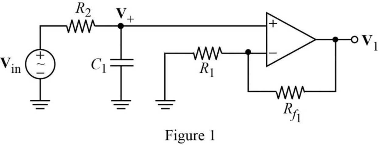
The s-domain circuit of the Figure 1 is drawn as Figure 2 using the equations (1) and (2).
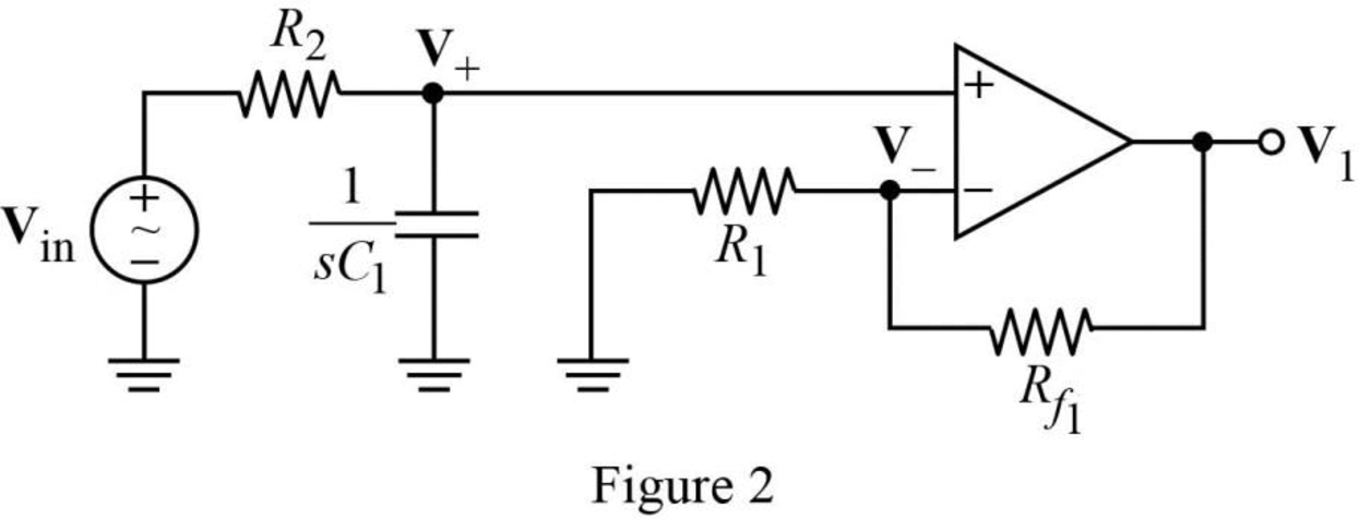
Write the general expression to calculate the transfer function of the circuit in Figure 2.
Here,
Use nodal analysis on node
Rearrange the above equation to find
Use nodal analysis on node
Rearrange the above equation to find
It is known that for an ideal operational amplifier,
Substitute
Rearrange the above equation to find
Substitute
Therefore, the equation (4) is the transfer function of the active low-pass filter that is the product of the transfer function of general low-pass filter and the gain of the non-inverting amplifier.
From equation (4), the gain of non-inverting amplifier is,
Write the general expression to calculate the voltage gain in dB.
Substitute
Rearrange the above equation to find
Assume the resistor,
Substitute
n (5).
Rearrange the above equation to find
Write the expression to calculate the corner frequency of the filter circuit shown in Figure 1.
Assume the capacitor,
Write the expression to calculate the bandwidth of the filter.
It is known that the corner frequency
Substitute
Rearrange the above equation to find
Substitute
Rearrange the above equation to find
For first stage low-pass filter,
High-pass filter design:
For high-pass filter, the voltage gain
The active high-pass op amp filter is drawn as Figure 3.
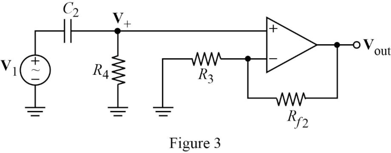
The s-domain circuit of the Figure 3 is drawn as Figure 4 using the equations (1) and (2).
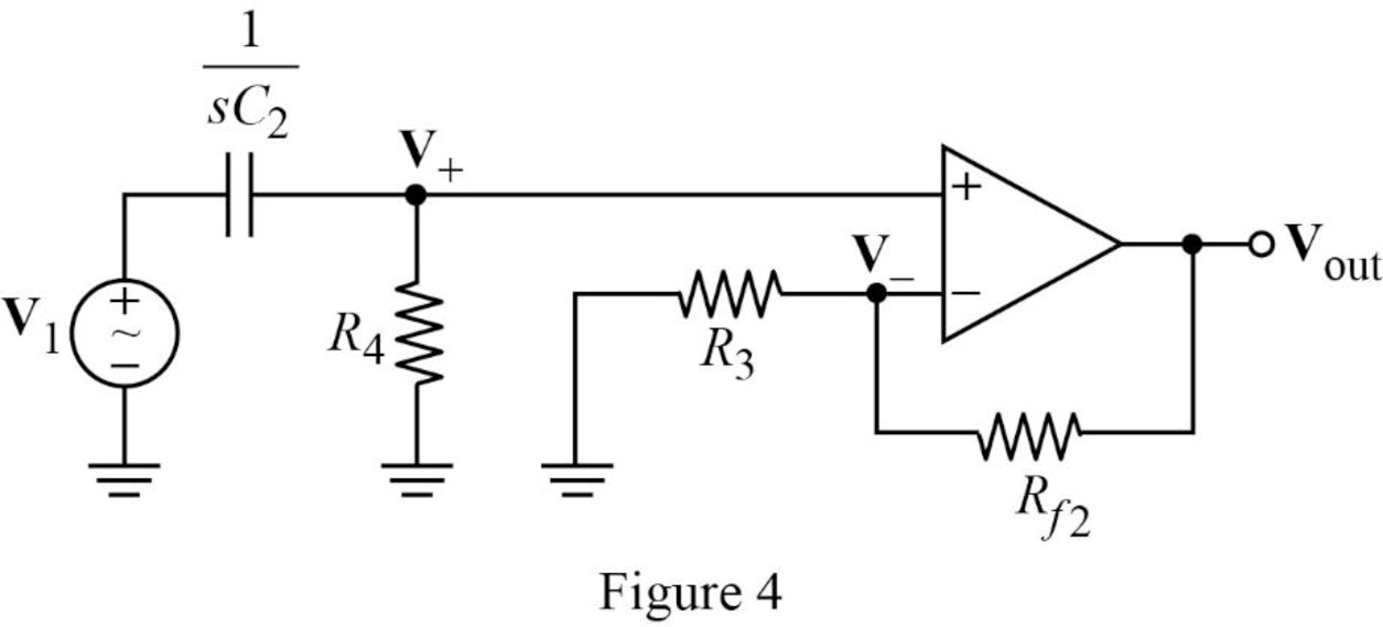
Write the general expression to calculate the transfer function of the circuit in Figure 4.
Here,
Use nodal analysis on node
Rearrange the above equation to find
Use nodal analysis on node
Rearrange the above equation to find
It is known that for an ideal operational amplifier,
Substitute
Rearrange the above equation to find
Substitute
Therefore, the equation (8) is the transfer function of the active high-pass filter that is the product of the transfer function of general high-pass filter and the gain of the non-inverting amplifier.
From equation (8), the gain of non-inverting amplifier is,
Write the general expression to calculate the voltage gain in dB.
Substitute
Rearrange the above equation to find
Assume the resistor,
Substitute
Rearrange the above equation to find
Write the expression to calculate the corner frequency of the filter circuit shown in Figure 4.
Assume the capacitor,
It is known that the corner frequency
Given that,
Substitute
Rearrange the above equation to find
Simplify the above equation to find
For second stage high-pass filter,
The two-stage op amp band-pass filter circuit is drawn as Figure 5.
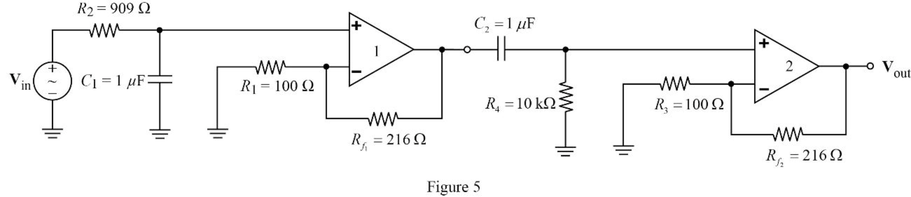
Conclusion:
Thus, the two-stage op amp filter circuit with a bandwidth of
(b)
Verify the two-stage op amp filter circuit design with an appropriate LTspice simulation.
Explanation of Solution
Calculation:
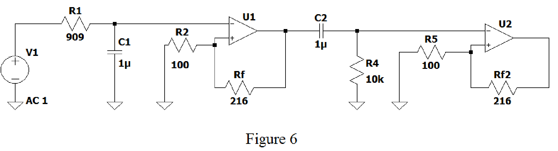
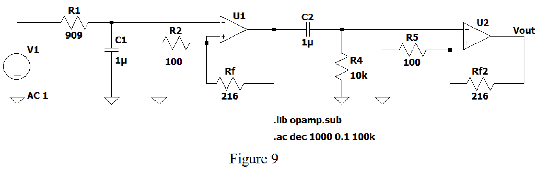
Create the new schematic in LTspice and draw the circuit in Figure 5 as shown in Figure 6 by entering the corresponding values of resistors and capacitors.
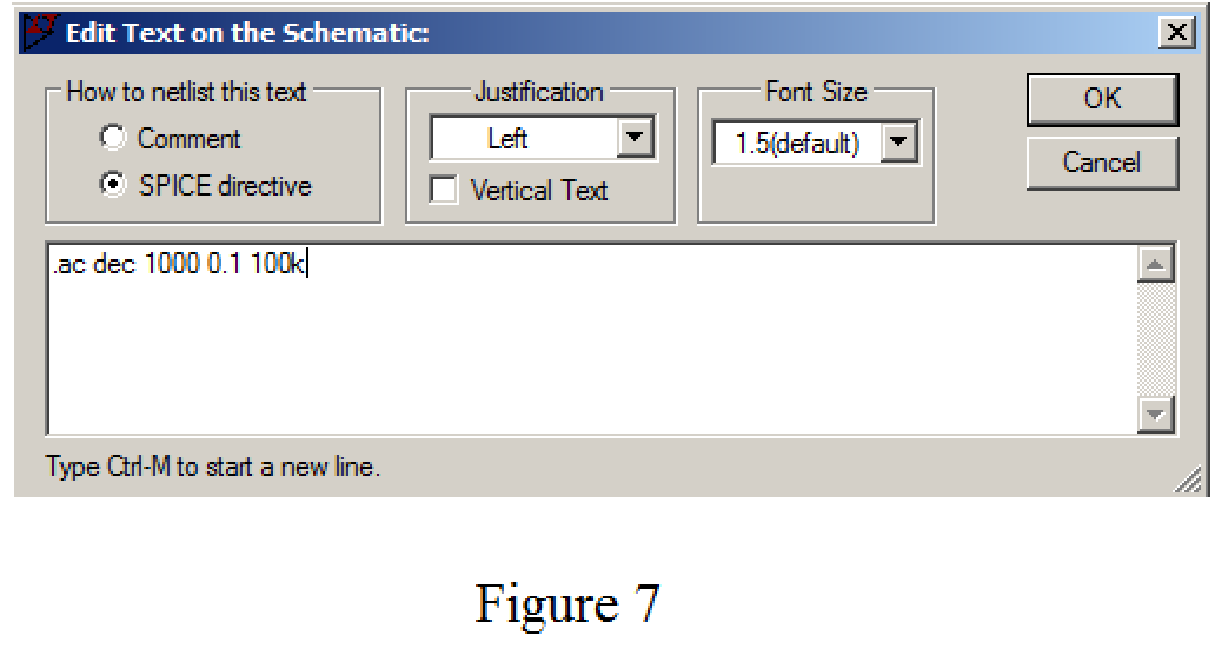
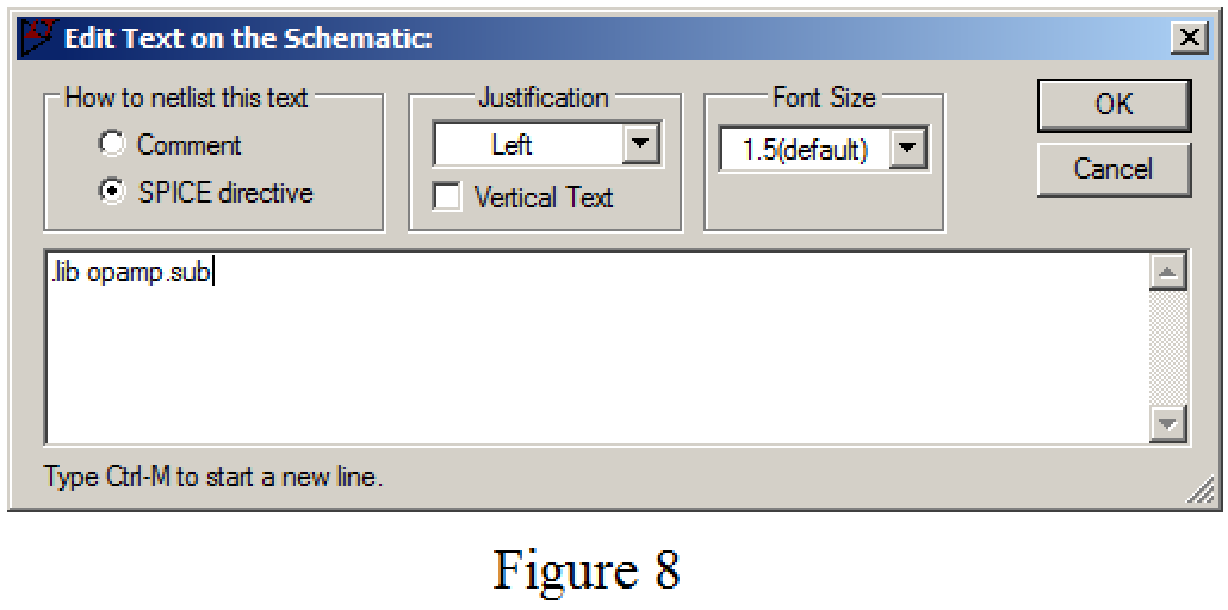
Using SPICE Directive in Edit menu, mention the command .ac dec 1000 0.1 100k and .lib opamp.sub as shown in Figure 7 and Figure 8.
Use Label Net option and enter the Vout. After adding all the commands mentioned above, the circuit is shown as in Figure 9.
Now run the simulation and place the probe at resistor
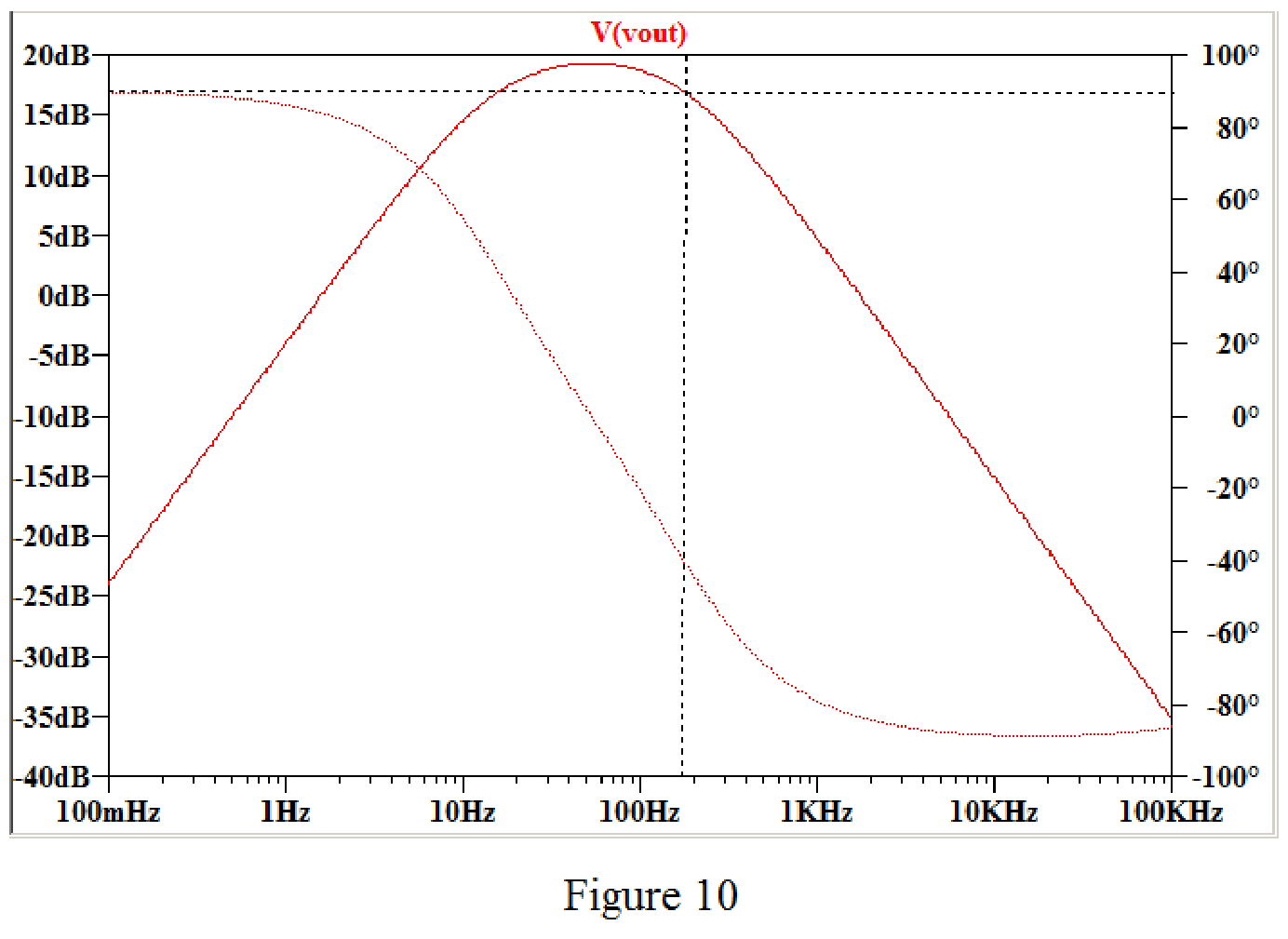
Refer to Figure 10 the thick red line indicates magnitude response, the dotted red line indicates phase response, and the black dotted line represents the corner frequency of the magnitude response.
Conclusion:
Thus, the design of the two-stage op amp filter is verified by using the LTspice simulation.
Want to see more full solutions like this?
Chapter 15 Solutions
Loose Leaf for Engineering Circuit Analysis Format: Loose-leaf
Additional Engineering Textbook Solutions
Basic Engineering Circuit Analysis
Principles and Applications of Electrical Engineering
Electric Circuits. (11th Edition)
Engineering Electromagnetics
Electronics Fundamentals: Circuits, Devices & Applications
Electric Motors and Control Systems


- What is a bandpass filter? How is its bandwidth defined?arrow_forward2. (a) The Band Pass filter(BPF) circuit that you have done in the lab, work on the principle of resonance. (b) The Band Reject filter(BRF) circuit that you have work done in the lab, the principle of on resonance. (c) What are the other possible circuits for BPF and BRF to get the same performance as above? Draw them below:arrow_forwardAn RLC series circuit is connected to a 20 V variable frequency supply as shown in Figure 2. Determine the following: O,SAF 202 20mH 20V Figure 2 Resonant frequency in Hertz. (b) Q-factor (c) Lower and upper half power frequencies in Hertz. (d) Bandwidth in Hertz and radians per second. (a)arrow_forward
- bessel bandpass filter analysis and all formula. lecture summaryarrow_forwardWhat is the transfer function of a filter? Describe how the transfer function of a filter can be determined using laboratory methods.arrow_forwardUse the image below to help answers parts a and b.in an LRC type circuit series the inductive reactance is XL=484 ohms. and I=0.8 amps is the measured current amplitude.A) In the inductor determine the amplitude of the voltage.B)If the LRC circuit is at resonance frequency find the capacitive reactance.arrow_forward
- Design an active high-pass filter circuit using op-amp and calculate the value ofthe capacitor, resistor needed that will produce the cut-off frequency of 331 Hz.arrow_forwardHigh-frequency ECG analysis in the ST-T segment of an ECG signal recording requires the analysis of signal components above 80 Hz and below 500 Hz. Design a first order band pass passive filter to accommodate this specified frequency bandwidth. Sketch the circuit configuration. You may use an op-amp buffer stage in your circuit designarrow_forwardWhat is a notch filter? What is one application?arrow_forward
- 5. We would like to build a filter which implements the Bode approximate gain plot given below. a) What type of filter is this? b) Write an expression for the frequency response, H(jw), in Bode form; c) Write an expression for the transfer function, H(s), in pole-zero form; d) Use the table of op-amp circuits to sketch a circuit which has this frequency response. You do NOT have to specify component (R and C) values. OdB 10 104 105 106arrow_forwardHow can I design an active filter circuit (just the low pass) using resistors, capacitors, and op-amps that will implement the transfer function. You will need to factor the function into cascade functions in order to make this easier. I jus want the drwan design with a litte explanation if possible.arrow_forwardBy inserting a resistor R3 in parallel with C in the high-pass filter in the figure, it becomes a circuit known as zero-pole, which is applied in the control.a) Draw the modified circuit, and find its transfer function so that its name is justified.b) Specify the component values for a zero frequency of 100 Hz, pole frequency of 1 kHz, and high frequency gain of 0 dB; draw a picture of its magnitude graph.arrow_forward
 Introductory Circuit Analysis (13th Edition)Electrical EngineeringISBN:9780133923605Author:Robert L. BoylestadPublisher:PEARSON
 Delmar's Standard Textbook Of ElectricityElectrical EngineeringISBN:9781337900348Author:Stephen L. HermanPublisher:Cengage Learning
 Programmable Logic ControllersElectrical EngineeringISBN:9780073373843Author:Frank D. PetruzellaPublisher:McGraw-Hill Education
 Fundamentals of Electric CircuitsElectrical EngineeringISBN:9780078028229Author:Charles K Alexander, Matthew SadikuPublisher:McGraw-Hill Education
 Electric Circuits. (11th Edition)Electrical EngineeringISBN:9780134746968Author:James W. Nilsson, Susan RiedelPublisher:PEARSON
 Engineering ElectromagneticsElectrical EngineeringISBN:9780078028151Author:Hayt, William H. (william Hart), Jr, BUCK, John A.Publisher:Mcgraw-hill Education,