
Loose Leaf for Engineering Circuit Analysis Format: Loose-leaf
9th Edition
ISBN: 9781259989452
Author: Hayt
Publisher: Mcgraw Hill Publishers
expand_more
expand_more
format_list_bulleted
Videos
Textbook Question
Chapter 15, Problem 69E
A piezoelectric sensor has an equivalent circuit representation as shown in Fig. 15.72. Determine (a) the transfer function H(s) = Vout/Vin; (b) plot the frequency response (Bode plot) for the case where Ce = 100 nF, C0 = 200 nF, Lm = 20 μH, and Ri = 50 kΩ, and (c) comment on the approximate frequency range where the sensor would be useful.
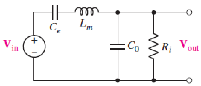
■ FIGURE 15.72
Expert Solution & Answer
Want to see the full answer?
Check out a sample textbook solution
Students have asked these similar questions
Help plz:
Design a Wein bridge oscillator to generate a sinusoidal waveform of frequency 5KHz.
Draw the spectrum of the followings modulated signal for the given case:
SSB(+)
SSB(-)+C
DSB LC
DSB SC
VSB + C
V:OV
3G !!.:
Classroom >
docs.google.com •
* الاسم الرباعي الكامل
Your answer
Engineering and Numerical Analysis
Lecture: Safa Al-waily
01| plot the Amplidude s phase spectyum
(signal & double side)
Q2 |Fimd x plot h complex form of (Fis)
for he fenetion.
Scanned by TapScanner
1 Add file
Submit
Clear form
Never submit passwords through Google Forms.
+
•..
5
Chapter 15 Solutions
Loose Leaf for Engineering Circuit Analysis Format: Loose-leaf
Ch. 15.1 - Write an expression for the transfer function of...Ch. 15.2 - Calculate HdB at = 146 rad/s if H(s) equals (a)...Ch. 15.2 - Prob. 3PCh. 15.2 - Draw the Bode phase plot for the transfer function...Ch. 15.2 - Construct a Bode magnitude plot for H(s) equal to...Ch. 15.2 - Draw the Bode phase plot for H(s) equal to (a)...Ch. 15.2 - Prob. 7PCh. 15.3 - A parallel resonant circuit is composed of the...Ch. 15.3 - Prob. 9PCh. 15.4 - A marginally high-Q parallel resonant circuit has...
Ch. 15.5 - A series resonant circuit has a bandwidth of 100...Ch. 15.6 - Referring to the circuit of Fig. 15.25a, let R1 =...Ch. 15.6 - Prob. 13PCh. 15.6 - Prob. 14PCh. 15.6 - The series combination of 10 and 10 nF is in...Ch. 15.7 - A parallel resonant circuit is defined by C = 0.01...Ch. 15.8 - Design a high-pass filter with a cutoff frequency...Ch. 15.8 - Design a bandpass filter with a low-frequency...Ch. 15.8 - Design a low-pass filter circuit with a gain of 30...Ch. 15 - For the RL circuit in Fig. 15.52, (a) determine...Ch. 15 - For the RL circuit in Fig. 15.52, switch the...Ch. 15 - Examine the series RLC circuit in Fig. 15.53, with...Ch. 15 - For the circuit in Fig. 15.54, (a) derive an...Ch. 15 - For the circuit in Fig. 15.55, (a) derive an...Ch. 15 - For the circuit in Fig. 15.56, (a) determine the...Ch. 15 - For the circuit in Fig. 15.57, (a) determine the...Ch. 15 - Sketch the Bode magnitude and phase plots for the...Ch. 15 - Use the Bode approach to sketch the magnitude of...Ch. 15 - If a particular network is described by transfer...Ch. 15 - Use MATLAB to plot the magnitude and phase Bode...Ch. 15 - Determine the Bode magnitude plot for the...Ch. 15 - Determine the Bode magnitude and phase plot for...Ch. 15 - Prob. 15ECh. 15 - Prob. 16ECh. 15 - For the circuit of Fig. 15.56, construct a...Ch. 15 - Construct a magnitude and phase Bode plot for the...Ch. 15 - For the circuit in Fig. 15.54, use LTspice to...Ch. 15 - For the circuit in Fig. 15.55, use LTspice to...Ch. 15 - Prob. 21ECh. 15 - A certain parallel RLC circuit is built using...Ch. 15 - A parallel RLC network is constructed using R = 5...Ch. 15 - Prob. 24ECh. 15 - Delete the 2 resistor in the network of Fig....Ch. 15 - Delete the 1 resistor in the network of Fig....Ch. 15 - Prob. 28ECh. 15 - Prob. 29ECh. 15 - Prob. 30ECh. 15 - A parallel RLC network is constructed with a 200 H...Ch. 15 - Prob. 32ECh. 15 - A parallel RLC circuit is constructed such that it...Ch. 15 - Prob. 34ECh. 15 - Prob. 35ECh. 15 - An RLC circuit is constructed using R = 5 , L = 20...Ch. 15 - Prob. 37ECh. 15 - Prob. 38ECh. 15 - For the network of Fig. 15.25a, R1 = 100 , R2 =...Ch. 15 - Assuming an operating frequency of 200 rad/s, find...Ch. 15 - Prob. 41ECh. 15 - Prob. 42ECh. 15 - For the circuit shown in Fig. 15.64, the voltage...Ch. 15 - Prob. 44ECh. 15 - Prob. 45ECh. 15 - Prob. 46ECh. 15 - The filter shown in Fig. 15.66a has the response...Ch. 15 - Prob. 48ECh. 15 - Examine the filter for the circuit in Fig. 15.68....Ch. 15 - Examine the filter for the circuit in Fig. 15.69....Ch. 15 - (a)Design a high-pass filter with a corner...Ch. 15 - (a) Design a low-pass filter with a break...Ch. 15 - Prob. 53ECh. 15 - Prob. 54ECh. 15 - Design a low-pass filter characterized by a...Ch. 15 - Prob. 56ECh. 15 - The circuit in Fig. 15.70 is known as a notch...Ch. 15 - (a) Design a two-stage op amp filter circuit with...Ch. 15 - Design a circuit which removes the entire audio...Ch. 15 - Prob. 61ECh. 15 - If a high-pass filter is required having gain of 6...Ch. 15 - (a) Design a second-order high-pass Butterworth...Ch. 15 - Design a fourth-order high-pass Butterworth filter...Ch. 15 - (a) Design a Sallen-Key low-pass filter with a...Ch. 15 - (a) Design a Sallen-Key low-pass filter with a...Ch. 15 - A piezoelectric sensor has an equivalent circuit...Ch. 15 - Design a parallel resonant circuit for an AM radio...Ch. 15 - The network of Fig. 15.72 was implemented as a...Ch. 15 - Determine the effect of component tolerance on the...
Additional Engineering Textbook Solutions
Find more solutions based on key concepts
For the “tank” circuit in Fig. 14.79, find the resonant frequency.
Figure 14.79
For Probs. 14.39, 14.71, and 1...
Fundamentals of Electric Circuits
A constant voltage of 10V is applied to a 50H inductance, as shown in Figure P3.51 Figure P3 51 The current in ...
Electrical Engineering: Principles & Applications (7th Edition)
Analog Voltmeter Design Figure P2-98(a) shows a voltmeter circuit consisting of a D'Arsonval meter, two series ...
ANALYSIS+DESIGN OF LINEAR CIRCUITS(LL)
What is the color code for a 365- five-band precision resistor with a tolerance of 5 percent?
ELECTRICITY FOR TRADES (LOOSELEAF)
Assume a telephone signal travels through a cable at two-thirds the speed of light. How long does it take the s...
Electric Circuits (10th Edition)
Identify the type of input and output configuration for each diff-amp in Figure 18-35.
Electronics Fundamentals: Circuits, Devices & Applications
Knowledge Booster


Learn more about
Need a deep-dive on the concept behind this application? Look no further. Learn more about this topic, electrical-engineering and related others by exploring similar questions and additional content below.Similar questions
- For a transistorized RC oscillator, select the value of capacitor C in order to provide 2 KHz oscillator frequency with resistance Rc=10kOhms, R=8KOhms. Given that Rc = 10 x 10^3 Hz, R = 8 x 10^3Hz, f = 2 x 10^3Hz. Show your solutions. 3 μF 0.003 μ F 3nF 0.3 μFarrow_forwardDesign (only the block diagram) an Armstrong indirect FM modulator to generate an FM carrier with a carrier frequency of 96 MHz and Af = 20 kHz. A narrow-band FM generator with fe = 200 kHz and adjustable Af in the range of 9 to 10 Hz is available. The stock room also has an oscillator with adjustable frequency in the range of 9 to 10 MHz. There is a bandpass filter with any center frequency, and only frequency doublers are available.arrow_forwardA vibration analyst wishes to record a frequency spectrum covering the range 0-10000 Hz with a resolution of 0.5 Hz. Calculate the necessary ADC sampling rate and also the necessary number of samples per spectrum.arrow_forward
- Given a Silicon PUT used in a relaxation oscillator with the following parameters: THE VBB- 10 V. R - 18kN, C-1 uF, RK - 1000. RB1 - 8 km, RB2 = 4 k, IP 100 µA, Vv 1 V, lv 5.0 mA, determine the period to reach the firing potential. 28 ms O 32 ms 0 24 ms 20 ms پالے 5arrow_forwardIt refers to the mixing of frequencies in a nonlinear device or the use of nonlinear mixing to convert one frequency to another. Select your answer. Frequency transformation Frequency mixing Superheterodyne Heterodynearrow_forwardPerform an 8-point DFT on a continuous input signal containing components at 1 kHz and 2 kHz, expressed as: Xn (t) = sin(2000nt) + 0.50sin (4000nt + 0.50) Xa(t)=sin(2000IIt)+0.50sin(4000+0.511) Created by SEASOFT LTD.arrow_forward
- For RL = 10k, meausre the voltage of the capacitor at one half of the period (take the orgin of time at the start of the first positive swing of the input signal)..arrow_forwardNOTE: Solve this as soon as possible, I need this urgently. a) The input and output voltages of a filter network are 8mV and 16mV, respectively. Calculate the decibel level of the output voltage. b) A wheel 50 cm in radius rotates 360°. What is the linear displacement of a point on the edge of the wheel?arrow_forwardDetermine if each statement is True or False; if false, please explain whya) A forced oscillator is when a system is being yelled at to perform a specific motion.b) Impedance is a measure of the total resistance a RLC series circuit has towards current.c) The phase angle tells us how “out-of-phase” the charge on the capacitor iswith the driving voltage.arrow_forward
- 1. A series RLC circuit has a Q of 75 and a pass band between half-power frequencies of 160 cps. Calculate the frequency of resonance and upper and lower frequencies of the pass band. 2. A 15.9 uF capacitor and a 15.1 mH inductor are connected in parallel. In series with these units are a variable resistor R and an adjustable device X, joined in series. (a) Determine the kind and size of device X (inductance in Henry or capacitance in Farad) when the circuit is connected to a 50 volt 400 cps source and is adjusted to resonance. (b) For the resonant condition, calculate the value of R if the voltage drop across the paralleled units is to be 100 volts. 3. An impedance coil having a resistance of 30 ohms and a 50 cps inductive reactance of 33.3 ohms is connected to a 125 volt 60 cps source. A series circuit consisting of a 20 ohm resistor and a variable capacitor is then connected in parallel with the coil. (a) for what values of capacitance will the circuit be in resonance? (b)…arrow_forward12:13 File Details 2222 ECET 3440 1 1001 LEC 129... ЕСЕТ-3440 Homework 7 (Full AM) NOTE: Complete/Solve all following problems using paper/pencil. Make it in one PDF file and upload it to Canvas. You can follow Camera Scan guidelines to convert your work into PDF. You can use Formula Sheet available on Canvas under Course Information. Problem 1 The output signal from an AM modulator is u(t) = 5 cos 1800nt + 20 cos 2000t + 5 cos2200t 1. Determine the modulating signal m(t) and the carrier c(t). 2. Determine the modulation index. 3. Determine the ratio of the power in the sidebands to the power in the carrier. Problem 2 An AM signal has the form gaM (t) = [50 + 40 cos(1000t)] cos(2nf.t) where fe 5 kHz. || (a) Sketch the spectrum of gam (t). (b) Determine the power in each of the frequency components. (c) Determine the modulation index. (d) Determine the sidebands' power, the total power, and the ratio of the sidebands' power to the total power. (e) Find the power efficiency. Problem 3 An…arrow_forward7. Refer to the Hartley Oscillator circuit, compute for wo and gm. L1 = 10mH, L2 = 20mH, R = 10kOhms, C = 100nF R LIS L₂ Carrow_forward
arrow_back_ios
SEE MORE QUESTIONS
arrow_forward_ios
Recommended textbooks for you
 Introductory Circuit Analysis (13th Edition)Electrical EngineeringISBN:9780133923605Author:Robert L. BoylestadPublisher:PEARSON
 Delmar's Standard Textbook Of ElectricityElectrical EngineeringISBN:9781337900348Author:Stephen L. HermanPublisher:Cengage Learning
 Programmable Logic ControllersElectrical EngineeringISBN:9780073373843Author:Frank D. PetruzellaPublisher:McGraw-Hill Education
 Fundamentals of Electric CircuitsElectrical EngineeringISBN:9780078028229Author:Charles K Alexander, Matthew SadikuPublisher:McGraw-Hill Education
 Electric Circuits. (11th Edition)Electrical EngineeringISBN:9780134746968Author:James W. Nilsson, Susan RiedelPublisher:PEARSON
 Engineering ElectromagneticsElectrical EngineeringISBN:9780078028151Author:Hayt, William H. (william Hart), Jr, BUCK, John A.Publisher:Mcgraw-hill Education,
Introductory Circuit Analysis (13th Edition)
Electrical Engineering
ISBN:9780133923605
Author:Robert L. Boylestad
Publisher:PEARSON
Delmar's Standard Textbook Of Electricity
Electrical Engineering
ISBN:9781337900348
Author:Stephen L. Herman
Publisher:Cengage Learning
Programmable Logic Controllers
Electrical Engineering
ISBN:9780073373843
Author:Frank D. Petruzella
Publisher:McGraw-Hill Education
Fundamentals of Electric Circuits
Electrical Engineering
ISBN:9780078028229
Author:Charles K Alexander, Matthew Sadiku
Publisher:McGraw-Hill Education
Electric Circuits. (11th Edition)
Electrical Engineering
ISBN:9780134746968
Author:James W. Nilsson, Susan Riedel
Publisher:PEARSON
Engineering Electromagnetics
Electrical Engineering
ISBN:9780078028151
Author:Hayt, William H. (william Hart), Jr, BUCK, John A.
Publisher:Mcgraw-hill Education,
David Sarnoff, Howard Armstrong & the Superheterodyne Receiver; Author: Kathy Loves Physics & History;https://www.youtube.com/watch?v=7eTfF67Ka5w;License: Standard Youtube License