
Loose Leaf for Engineering Circuit Analysis Format: Loose-leaf
9th Edition
ISBN: 9781259989452
Author: Hayt
Publisher: Mcgraw Hill Publishers
expand_more
expand_more
format_list_bulleted
Concept explainers
Videos
Textbook Question
Chapter 15.6, Problem 12P
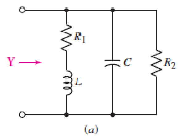
Referring to the circuit of Fig. 15.25a, let R1 = 1 kΩ and C = 2.533 pF. Determine the inductance necessary to select a resonant frequency of 1 MHz. (Hint: Recall that ω = 2π f.)
Expert Solution & Answer
Want to see the full answer?
Check out a sample textbook solution
Students have asked these similar questions
The amplitude plot rises as the frequency increases from 100 Hz until
the
is reached
input frequency
resonant frequency
gain
emf
The lead-lag network, at resonance, shows an output voltage that is
the input voltage
half
double
one-third
same
first, the capacitor starts to discharge via the inductor, which results in
the conversion of its electrical energy into the
microwave energy
static electricity
electromagnetic field
noise voltage
1:53:24 C
RLC circuit with a sinusoidal input voltage, the amplitude of the current passing through the circuit (lo in mA) is
plotted as a function of frequency for two cases
Curve 1 with Ry, L1, and
.Curve 2 with R, L2 as shown in the next figure
The value of the capacitor used in the circuits is C=0.01 micro Farads
:The quality factor (Q1) for curve 1 is about
7.5
5-
2.5
I to
1 10
I 10
I to
Frequency (f), H
Consider the following frequency selective circuit. At what
frequency, in hertz, will the magnitude of H(jw) equal zero?
Given R = 22 , L = 250 mH, C = 10 mF.
L
C
R
Vo
Chapter 15 Solutions
Loose Leaf for Engineering Circuit Analysis Format: Loose-leaf
Ch. 15.1 - Write an expression for the transfer function of...Ch. 15.2 - Calculate HdB at = 146 rad/s if H(s) equals (a)...Ch. 15.2 - Prob. 3PCh. 15.2 - Draw the Bode phase plot for the transfer function...Ch. 15.2 - Construct a Bode magnitude plot for H(s) equal to...Ch. 15.2 - Draw the Bode phase plot for H(s) equal to (a)...Ch. 15.2 - Prob. 7PCh. 15.3 - A parallel resonant circuit is composed of the...Ch. 15.3 - Prob. 9PCh. 15.4 - A marginally high-Q parallel resonant circuit has...
Ch. 15.5 - A series resonant circuit has a bandwidth of 100...Ch. 15.6 - Referring to the circuit of Fig. 15.25a, let R1 =...Ch. 15.6 - Prob. 13PCh. 15.6 - Prob. 14PCh. 15.6 - The series combination of 10 and 10 nF is in...Ch. 15.7 - A parallel resonant circuit is defined by C = 0.01...Ch. 15.8 - Design a high-pass filter with a cutoff frequency...Ch. 15.8 - Design a bandpass filter with a low-frequency...Ch. 15.8 - Design a low-pass filter circuit with a gain of 30...Ch. 15 - For the RL circuit in Fig. 15.52, (a) determine...Ch. 15 - For the RL circuit in Fig. 15.52, switch the...Ch. 15 - Examine the series RLC circuit in Fig. 15.53, with...Ch. 15 - For the circuit in Fig. 15.54, (a) derive an...Ch. 15 - For the circuit in Fig. 15.55, (a) derive an...Ch. 15 - For the circuit in Fig. 15.56, (a) determine the...Ch. 15 - For the circuit in Fig. 15.57, (a) determine the...Ch. 15 - Sketch the Bode magnitude and phase plots for the...Ch. 15 - Use the Bode approach to sketch the magnitude of...Ch. 15 - If a particular network is described by transfer...Ch. 15 - Use MATLAB to plot the magnitude and phase Bode...Ch. 15 - Determine the Bode magnitude plot for the...Ch. 15 - Determine the Bode magnitude and phase plot for...Ch. 15 - Prob. 15ECh. 15 - Prob. 16ECh. 15 - For the circuit of Fig. 15.56, construct a...Ch. 15 - Construct a magnitude and phase Bode plot for the...Ch. 15 - For the circuit in Fig. 15.54, use LTspice to...Ch. 15 - For the circuit in Fig. 15.55, use LTspice to...Ch. 15 - Prob. 21ECh. 15 - A certain parallel RLC circuit is built using...Ch. 15 - A parallel RLC network is constructed using R = 5...Ch. 15 - Prob. 24ECh. 15 - Delete the 2 resistor in the network of Fig....Ch. 15 - Delete the 1 resistor in the network of Fig....Ch. 15 - Prob. 28ECh. 15 - Prob. 29ECh. 15 - Prob. 30ECh. 15 - A parallel RLC network is constructed with a 200 H...Ch. 15 - Prob. 32ECh. 15 - A parallel RLC circuit is constructed such that it...Ch. 15 - Prob. 34ECh. 15 - Prob. 35ECh. 15 - An RLC circuit is constructed using R = 5 , L = 20...Ch. 15 - Prob. 37ECh. 15 - Prob. 38ECh. 15 - For the network of Fig. 15.25a, R1 = 100 , R2 =...Ch. 15 - Assuming an operating frequency of 200 rad/s, find...Ch. 15 - Prob. 41ECh. 15 - Prob. 42ECh. 15 - For the circuit shown in Fig. 15.64, the voltage...Ch. 15 - Prob. 44ECh. 15 - Prob. 45ECh. 15 - Prob. 46ECh. 15 - The filter shown in Fig. 15.66a has the response...Ch. 15 - Prob. 48ECh. 15 - Examine the filter for the circuit in Fig. 15.68....Ch. 15 - Examine the filter for the circuit in Fig. 15.69....Ch. 15 - (a)Design a high-pass filter with a corner...Ch. 15 - (a) Design a low-pass filter with a break...Ch. 15 - Prob. 53ECh. 15 - Prob. 54ECh. 15 - Design a low-pass filter characterized by a...Ch. 15 - Prob. 56ECh. 15 - The circuit in Fig. 15.70 is known as a notch...Ch. 15 - (a) Design a two-stage op amp filter circuit with...Ch. 15 - Design a circuit which removes the entire audio...Ch. 15 - Prob. 61ECh. 15 - If a high-pass filter is required having gain of 6...Ch. 15 - (a) Design a second-order high-pass Butterworth...Ch. 15 - Design a fourth-order high-pass Butterworth filter...Ch. 15 - (a) Design a Sallen-Key low-pass filter with a...Ch. 15 - (a) Design a Sallen-Key low-pass filter with a...Ch. 15 - A piezoelectric sensor has an equivalent circuit...Ch. 15 - Design a parallel resonant circuit for an AM radio...Ch. 15 - The network of Fig. 15.72 was implemented as a...Ch. 15 - Determine the effect of component tolerance on the...
Additional Engineering Textbook Solutions
Find more solutions based on key concepts
Write the nodal equations for the network of Fig. 8.137 using the general approach. Find the nodal voltages usi...
Introductory Circuit Analysis (13th Edition)
Analog Voltmeter Design Figure P2-98(a) shows a voltmeter circuit consisting of a D'Arsonval meter, two series ...
ANALYSIS+DESIGN OF LINEAR CIRCUITS(LL)
Assume a telephone signal travels through a cable at two-thirds the speed of light. How long does it take the s...
Electric Circuits (10th Edition)
What is the color code for a 365- five-band precision resistor with a tolerance of 5 percent?
ELECTRICITY FOR TRADES (LOOSELEAF)
How many coulombs do 93.8 1016 electrons represent?
Principles Of Electric Circuits
Three point charges of equal magnitude q, that will yield a zero net electric field at the origin.
Engineering Electromagnetics
Knowledge Booster


Learn more about
Need a deep-dive on the concept behind this application? Look no further. Learn more about this topic, electrical-engineering and related others by exploring similar questions and additional content below.Similar questions
- 5. Determine whether the following signals is periodic or not. If periodic, find the fundamental period and fundamental frequency. a) g(t) = 8 sin(400nt) + 2cos (500tt) 2nn 2 πη. b) g[n] = 5 cos () + sin () 8 6. Graph even and odd parts of the following signal. x[n] = rect5[n + 2] CS CamScanner - Wguo sguaallarrow_forwardFor the series RLC circuit shown, the frequency of the voltage source v, 20cos(@) V is %3D adjusted until the resonant frequency (@o) is reached. Under this resonance condition, the inductive reactance X is 38 2 and the maximum amplitude of the current i is 2.5 A. The resonant frequency in kHz is R ll :0. 1µF 1's O A. 263.16 O B. 1653.47 O C 41.88 O D. 41882.88arrow_forwardConsider the following Circuit, Find Zeq seen at points A and B: Given a 1 and b 14 Place the magnitude of Zeq in the space provided. 1 j -2j -bj 2j a A B Zegarrow_forward
- A power supply with rms voltage 400V and frequency 50HZ is equipped with a resonant harmonic filter to eliminate the 9th harmonic component. If C = 200µF and R = 40mn, calculate the inductance in the resonant harmonic filter, and the power quality factor.arrow_forwardA series RLC circuit consists of an 9.80-2 resistor, a 5.00-μF capacitor, and a 50.0-mH inductor. A variable-frequency source applies an emf of 430 V (rms) across the combination. Assuming the frequency is equal to one-half the resonance frequency, determine the power delivered to the circuit. Warrow_forwardткл R₁ Derive 29кл Rf an frequency 100nF 100nF 100nF +1 HITHE 12608 260 260 Vm an expression for oscillation 7777 Et A Yout This circuit and of show that the RC feed back network has attenuation of 1/29 at this frequencyarrow_forward
- A sinusoidal voltage V(t)=(200 V) sin ot is applied to a series RLC circuit with L=10.0 mH, C=100 nF and R=20.0 52. Find the following quantities: (a) the resonant frequency, (b) the amplitude of the current at resonance, c. Find the instantaneous voltage across each element v(t) d. Sketch the Phasor Diagram and state whether the circuit is inductive or capacitive. Why?arrow_forwardA Series R-L-C circecit has sinusoidal input voltage is 12 V. If inductance L=20mH, Resistance R =802 and capacitance, c = 400 nf, Determine the p.d accross the capacitor at the resonant frequency?.arrow_forward(b) A power supply with rms voltage 380V and frequency 50HZ is equipped with a resonant harmonic filter to eliminate the 7th harmonic component. If C = 200µF and R = 40mn, calculate the inductance in the resonant harmonic filter, and the power quality factor.arrow_forward
- A sinusoidal signal with a frequency of 100 Hz is used to modulate a carrier signal with a frequency of 0.5 kHz by DSB amplitude modulation. Which of the images below represents the spectrum of the modulated signal? Select one: O a. O b. magnitude magnitude 200 180 160 140 120 100 80 60 40 20 0 200 180 160 140 120 100 80 60 40 20 0 0 0 500 500 1000 1500 frequency (Hz) 1000 1500 frequency (Hz) 2000 2000 2500 2500 O c. d. magnitude magnitude 250 200 150 100 50 0 200 180 160 0 140 120 100 80 60 40 20 8° 0 0 500 500 1000 1500 frequency (Hz) 1000 1500 frequency (Hz) 2000 2000 2500 2500arrow_forwardA television channel is assigned the frequency range from 54MHZ to 60MHZ. A series RLC tuning circuit in a TV receiver resonates in the middle this frequency range. The circuit uses a 16PF capacitor. a. Solve for the value of the inductor. (0.49µH) b. In order to function properly, the current throughout the frequency range must be at least 50% of the current at the resonance frequency. What is the minimum possible value of the circuit's resistance such that the current at the frequency range bounds is 50% that at the resonance frequency? (10.32)arrow_forwardLet m(t) and its spectrum as follow: X (w) T= G0M 10 -Wm Wm a. Find the fundamental frequency (fm). b. If m(t) is to be modulated by a carrier with fc = 50 fm . Find fc c. If Am is used, draw the modulated wave in time and frequency domain at n=0.5 d. Design a demodulator circuit e. If DSB-SC is used, sketch the modulated signal in time and frequency domain.arrow_forward
arrow_back_ios
SEE MORE QUESTIONS
arrow_forward_ios
Recommended textbooks for you
 Introductory Circuit Analysis (13th Edition)Electrical EngineeringISBN:9780133923605Author:Robert L. BoylestadPublisher:PEARSON
 Delmar's Standard Textbook Of ElectricityElectrical EngineeringISBN:9781337900348Author:Stephen L. HermanPublisher:Cengage Learning
 Programmable Logic ControllersElectrical EngineeringISBN:9780073373843Author:Frank D. PetruzellaPublisher:McGraw-Hill Education
 Fundamentals of Electric CircuitsElectrical EngineeringISBN:9780078028229Author:Charles K Alexander, Matthew SadikuPublisher:McGraw-Hill Education
 Electric Circuits. (11th Edition)Electrical EngineeringISBN:9780134746968Author:James W. Nilsson, Susan RiedelPublisher:PEARSON
 Engineering ElectromagneticsElectrical EngineeringISBN:9780078028151Author:Hayt, William H. (william Hart), Jr, BUCK, John A.Publisher:Mcgraw-hill Education,
Introductory Circuit Analysis (13th Edition)
Electrical Engineering
ISBN:9780133923605
Author:Robert L. Boylestad
Publisher:PEARSON
Delmar's Standard Textbook Of Electricity
Electrical Engineering
ISBN:9781337900348
Author:Stephen L. Herman
Publisher:Cengage Learning
Programmable Logic Controllers
Electrical Engineering
ISBN:9780073373843
Author:Frank D. Petruzella
Publisher:McGraw-Hill Education
Fundamentals of Electric Circuits
Electrical Engineering
ISBN:9780078028229
Author:Charles K Alexander, Matthew Sadiku
Publisher:McGraw-Hill Education
Electric Circuits. (11th Edition)
Electrical Engineering
ISBN:9780134746968
Author:James W. Nilsson, Susan Riedel
Publisher:PEARSON
Engineering Electromagnetics
Electrical Engineering
ISBN:9780078028151
Author:Hayt, William H. (william Hart), Jr, BUCK, John A.
Publisher:Mcgraw-hill Education,
Understanding Frequency Modulation; Author: Rohde Schwarz;https://www.youtube.com/watch?v=gFu7-7lUGDg;License: Standard Youtube License